215585 70 Revision A
$
%%
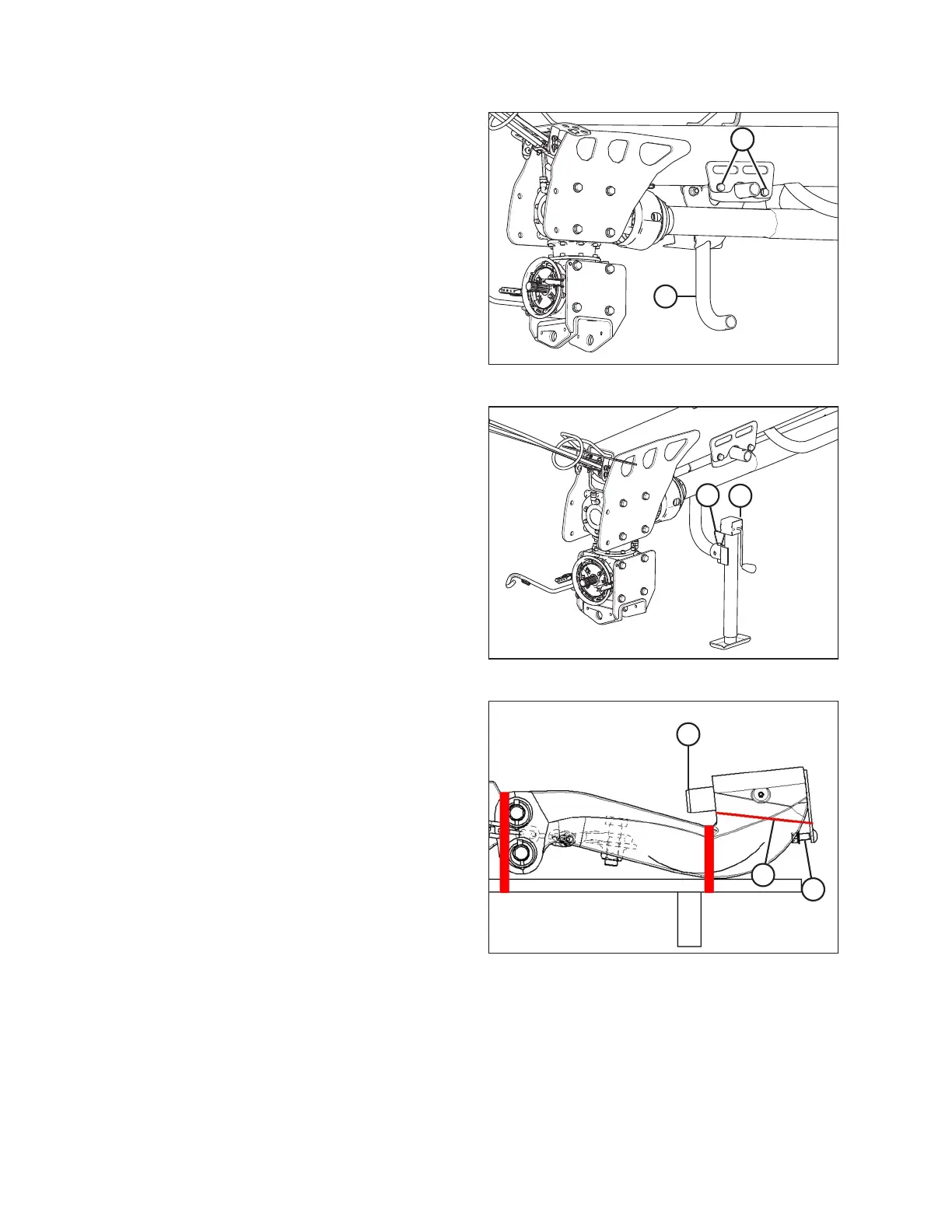
Figure 4.24: Jack Stand Support
6. Install jack support stand (A) as shown. Secure with two
M12 x 1.75 x 40 bolts (B), M12 washers, and M12 center
lock nuts per side. Torque hardware to 69 Nm (51 lbf·ft).
$
%
Figure 4.25: Jack Stand
7. Install jack (A) at front of hitch, and secure with pin (B).
8. Lower forklift until hitch is resting on jack (A).
$
%
&
Figure 4.26: Hitch Casting
9. Remove shipping wire (A) that secures pin (B) in casting. Do
NOT remove other strapping.
10. Remove pin (B) from casting, and remove bolt (C) and nut
from pin.
ASSEMBLING THE ROTARY DISC PULL-TYPE – FACTORY-INSTALLED TRANSPORT