215585 86 Revision A
$
%
&
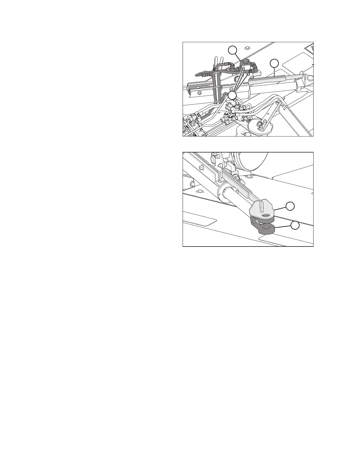
Figure 4.62: Alignment Control – Rear Right View
2. Check travel of cam arm (A) by sliding it in and out of cam
assembly (B).
NOTE:
If the cam arm does NOT slide easily, loosen valve
mounting bolts (C), and slide valve (B) up to the top of the
mounting holes. Retighten valve mounting bolts (C).
$
%
Figure 4.63: Alignment Control – Rear Right View
3. Align hole in cam arm (A) with hole in clevis (B) at the rod
end of the cylinder.
ASSEMBLING THE ROTARY DISC PULL-TYPE – FACTORY-INSTALLED TRANSPORT