4-41
TMS800E SERVICE MANUAL BOOM
Published 01-29-2014, Control # 496-00
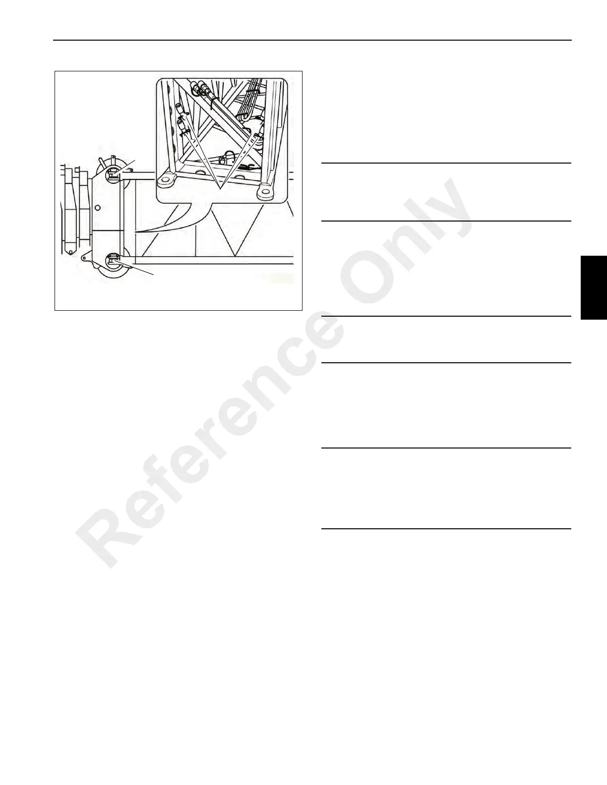
• Using an auxiliary crane with sling, lift the 5 m (16 ft)
section with support roller on an auxiliary crane and lift it
in front of the main boom head so that the bearing points
(2) and (3) align on both sides.
• Insert the securing pins into the bearing points (2) and
(3) on both sides.
• Secure all pins with retaining pins.
• Install the second 5 m (16 ft) section in front of the first
16 ft section for the 27 m (89 ft) jib in the same way.
• Install 17 m (56 ft) section in front of the respective 5 m
(16 ft) section per previous instructions in this section.
Removing the 5 m (16 ft) Sections
• Using an auxiliary crane with sling, lift the 5 m (16 ft)
section until the bearing points (2) and (3) are relieved.
• Release the pins and knock them out of the bearing
points (2) and (3) on both sides.
• Insert the pins into the holders at the foot of the 5 m (16
ft) sections and secure them with retaining needles.
JIB (ADDITIONAL EQUIPMENT)
Identification and Slinging Points
Identification
The jib consists of the 56 ft (17 m) bi-fold swingaway lattice
extension and two jib sections. The jib is designed for the
crane it was delivered with. The parts which belong to the
crane have the same serial number as the crane.
The following sections are identified by the serial number:
- All parts of the 17 m (56 ft) bi-fold swingaway lattice
extension.
- Both sections of the insert 5 m (16 ft) sections
.
NOTE: For technical reasons a crane may only be set with
one jib.
If you wish to use the jib on several Manitowoc/Grove
cranes, the parts of the jib must be adjusted for these cranes
and labeled with all of the respective serial numbers.
Serial numbers on the 5m (16ft) sections
The serial number is on a plate at the front of the 5 m (16 ft)
inserts.
Slinging Points
The 5 m (16 ft) sections have two slinging points (one slightly
offset on each side).
NOTE: For electrical connections at the 5 m (16 ft)
sections, refer to Electrical Connections at the Jib,
in this section.
ASSEMBLY OF JIBS
NOTE: The lengths of 22 m (72 ft) and 27 m (89 ft)
respectively equal the distance between the center
of the locking pin (on the main boom head) and the
front edge of the head sheave.
CAUTION
Operate the crane only with those sections of the jib which
have the same serial number as the crane. This prevents
malfunctions and damage.
CAUTION
Have the adjustment of the jib only carried out on site by
Manitowoc Crane Care!
CAUTION
This section shows the slinging points of the 16 ft (5 m)
sections. Attach the sections only to these slinging points
because they will then automatically have the correct
center of gravity. Use only lifting gear with sufficient load
bearing capacity.
Reference Only
 Loading...


