5-10
Published 01-29-2014, Control # 496-00
HOIST AND COUNTERWEIGHT TMS800E SERVICE MANUAL
HOIST DRUM INDICATOR SYSTEM
Description
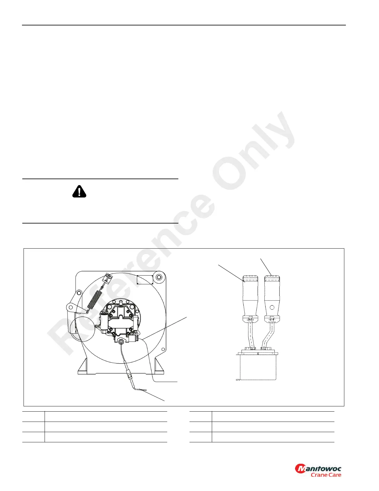
The hoist drum rotation indicator system (see Figure 5-4) is
an electrically operated system that provides the operator
with a touch indication of drum rotation so the operator will
know if and at what speed the hoist drum is rotating, even
under the most distracting conditions.
The rotation indicator system consists of the rotation
indicator sensor and thumb thumper solenoid. The rotation
sensor is located on the hoist. The pulsing thumb thumper
solenoid is located in the applicable hoist control lever
handle. Actuation of the thumb thumper is controlled by the
CAN-bus system from input supplied by the rotation indicator
sensor.
Maintenance
General
Proper circuit operation can be checked for each individual
electrical component. If a malfunction occurs within the
system, repairs should be limited to finding and replacing the
faulty component(s). To determine which component is at
fault, refer to the troubleshooting section of your CAN-bus
CD.
Rotation Sensor
The rotation sensor is screwed into the hoist housing and
senses the rotation of the primary drive end teeth. When
installing the sensor, ensure it contacts the top land of a tooth
and not between teeth. Screw the sensor in until contact is
made, then back out 1/2 turn and tighten lock nut.
Thumb Thumper Solenoid
The thumb thumper solenoid provides feedback proportional
to the hoist line speed by pulsing the rubber button on top of
the hoist controller. The thumb thumper will cease operation
at high line speeds to prevent damage to the solenoid.
Troubleshooting
NOTE: This machine incorporates a CAN bus Multiplex
system. In order to effectively troubleshoot the
electrical system, you need a Windows-based PC,
Orchestra® software (999102409), a connection
cable (9999102296) and a dongle (9999102587).
The Orchestra® software, connection cable and
dongle may be ordered from Crane Care.
CAUTION
Disconnect the batteries before performing any
maintenance on this system. Serious burns may result
from accidental shorting or grounding of live circuits.
FIGURE 5-4
1
Single Axis Controller
2
4
3
Hoist
6570
Item Description
1 Thumb Thumper
2 Controller
Item Description
3 To Rotation Indicators
4 High Speed Solenoid Connection
Reference Only
 Loading...


