8-48
Published 01-29-2014, Control # 496-00
UNDERCARRIAGE TMS800E SERVICE MANUAL
Air System Operational Test
NOTE: Refer to Figure 8-65 for air tank and valve
installation.
1. Park the crane on a firm level surface and apply the
parking brakes.
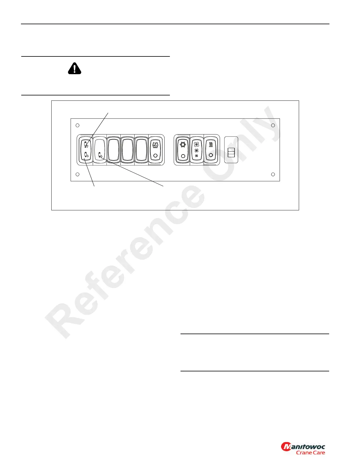
2. Push air suspension switch (Figure 8-66) in the carrier
cab to deflate position to deflate the air suspension
bags. The amber suspension deflate indicator light
should illuminate when the pressure in all air bags drops
below 0.28 ± 0.14 bar (4 ± 2 psi).
3. Raise the crane on outriggers.
4. Shutdown the engine.
Pressure Warnings and Pressure Build-up
1. Drain all reservoirs to zero (0) psi by opening the drain
valves. If not already applied, the parking brake will be
applied as the system is drained. Ensure the parking
brakes are applied on all rear wheels.
2. Close the drain valves and start the engine. Set the
engine speed to fast idle.
a. The low air pressure indicator (Figure 8-67) should
be on, and an audio warning should be on until both
pressure gauges indicate 4.14 to 4.83 bar (60 to 70
psi) air pressure.
b. Air will fill the primary (rear) or secondary (front)
reservoirs first. The red needle on the gauge
represents the primary air pressure. The green
needle on the gauge represents the secondary air
pressure. The primary or secondary gauge should
rise until it reaches 7.31 ± 0.41 bar (106 ± 6 psi). At
7.31 ± 0.41 bar (106 ± 6 psi), the pressure
protection valve will open and allow air to flow into
the reservoirs. The pressure will level off, or
momentarily fall as the next pressure protection
valve opens for the other system. When the other
systems reach 7.31 ± 0.41 bar (106 ± 6 psi), the
pressure will level off, or momentarily fall as the third
and fourth pressure protection valves open. Then
the primary and secondary gauges should increase
together until they reach their full pressure.
WARNING
Death or injury could occur!
Air pressure must not exceed 9.00 bar (130 psi).
Air Suspension Switch (Inflate Position)
Suspension Deflate Indicator
6906
Air Suspension Switch (Deflate Position)
FIGURE 8-66
CAUTION
Damage could occur!
Do not attempt to adjust or service the pressure protection
valves.
Reference Only
 Loading...


