8-72
Published 01-29-2014, Control # 496-00
UNDERCARRIAGE TMS800E SERVICE MANUAL
Outrigger Stabilizer Cylinder Internal Leak Test
Use the following procedure to troubleshoot and diagnose an
internal leak, a leaking pilot operated check valve or a
thermal contraction on an outrigger stabilizer cylinder.
Checking Cylinder for Internal Piston Seal Leak
1. Fully extend and set the outriggers.
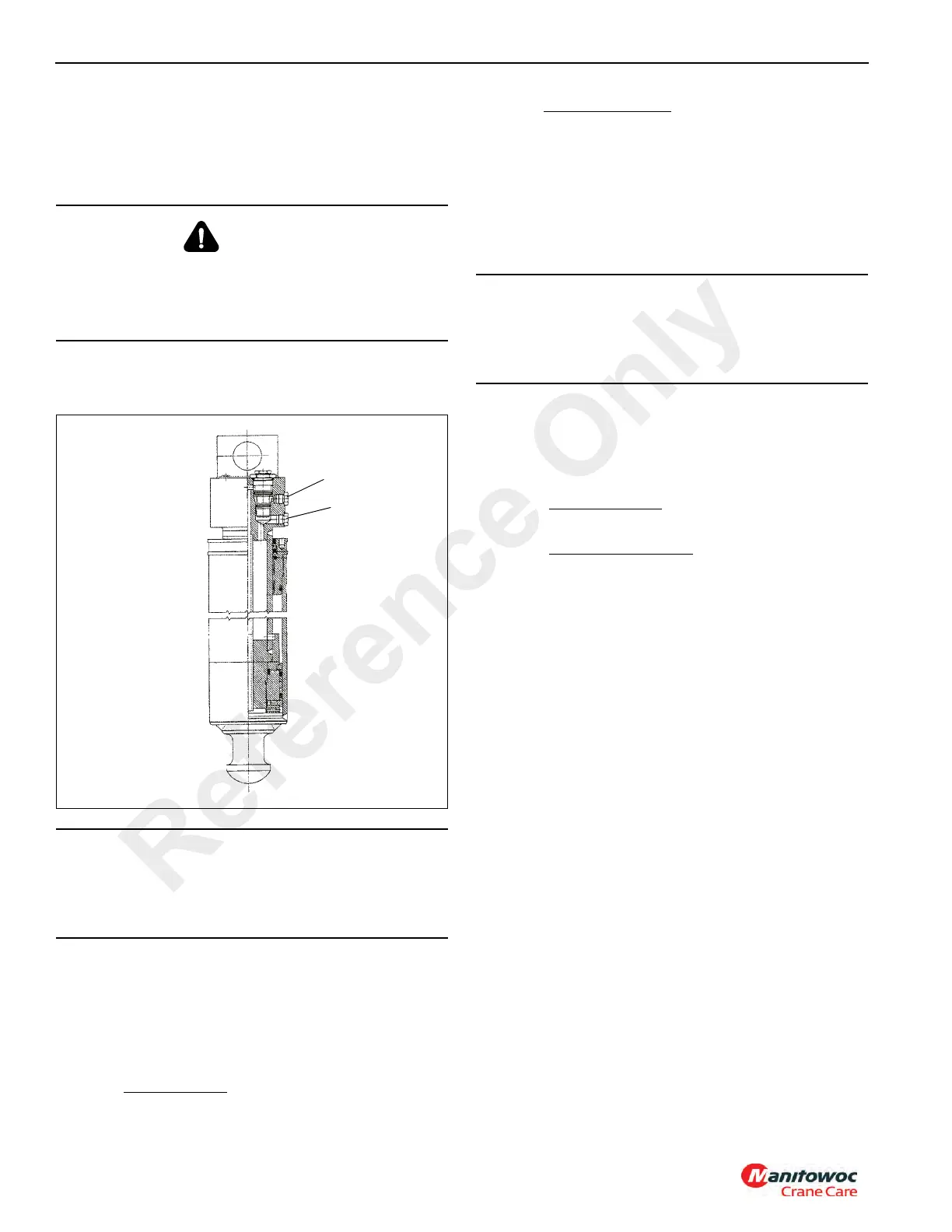
2. Remove the rod side cylinder hose from the suspected
leaking stabilizer cylinder (see Figure 8-78). Oil will flow
until the cavity in the cylinder port block empties. Once
the port block cavity empties, oil should stop flowing
from the rod side port.
Check for the following conditions:
a. If oil stops flowing
, the cylinder’s internal piston seal
is sealing properly.
b. If oil continues to flow
out the rod port, the cylinder’s
internal piston seal is leaking.
3. After determining the condition of the cylinders internal
piston seal, leave the rod side hose disconnected and
continue to test the pilot operated check valve.
Testing Pilot Operated Check Valve for Leakage
1. Fully extend and set the outriggers.
2. Remove the piston side cylinder hose from the
suspected leaking stabilizer cylinder (see Figure 8-78).
Oil will flow until the cavity in the cylinder port block
empties. Once the port block cavity empties, oil should
stop flowing from the piston side port.
a. If oil stops flowing
, the cylinder’s pilot operated
check valve is sealing properly.
b. If oil continues to flow
out the piston port, the
cylinder’s pilot operated check valve is leaking.
If oil flow is not noticed from either port, the cylinder and pilot
operated check valve are functioning properly, and any
cylinder contraction during normal operation can be
attributed to thermal contraction of the oil.
OUTRIGGER SYSTEM VALVES
Description
There are five valve assemblies responsible for controlling
the outrigger system, the outrigger selector valve, the front
and rear outrigger control manifolds, and the pilot operated
check valves.
NOTE: For a more detailed DESCRIPTION and
MAINTENANCE of the valves, refer to Valves,
page 2-22.
Pilot Operated Check Valve
The pilot operated check valves are located in the outrigger
stabilizer port blocks. The check valve provides two
functions; the first function is a holding valve, the second
function provides a thermal relief of the stabilizer.
Outrigger Selector Valve
The integrated outrigger is mounted on the center of carrier
frame in bearing area. The valve contains a 214 bar (3100
psi) relief valve and a two position two way solenoid valve
that is normally open by passing oil from the inlet port to the
tank port. The valve also contains a three position four way
DANGER
Perform the following procedures with the crane
positioned on a firm level surface with outriggers fully
extended and set, and the crane in the travel position.
Remove hoses from one cylinder at a time.
CAUTION
When performing step number 2, remove hose to adapter
connection slowly. Trapped pressure may exit between
the outrigger cylinder and the work port pilot operated
check valves in the outrigger selector valve.
FIGURE 8-78
Piston Port
Rod Port
6432
CAUTION
When performing step number 2, remove hose to adapter
connection slowly. Trapped pressure may exit between
the outrigger cylinder and the work port pilot operated
check valves in the outrigger selector valve.
Reference Only
 Loading...


