7-10
Published 01-29-2014, Control # 496-00
POWER TRAIN TMS800E SERVICE MANUAL
speed as needed. The cycle will take approximately 20
minutes.
Engine Stop Light
The engine stop light is located at the top left side of the front
console in the carrier cab. It is a red indicator light that
illuminates to signify a serious engine problem that requires
the vehicle and the engine to be stopped as soon as safely
possible.
Engine Warning Light
The engine warning light is located at the top left side of the
front console in the carrier cab. It is an amber indicator light
that is a part of the engine’s electronic control system and
when illuminated, gives the operator a signal that there is an
engine problem which must be corrected.
Engine Regeneration Inhibit Switch
This switch located in the right side overhead control panel is
used to stop an engine regeneration.
FUEL SYSTEM
Description
The fuel system consists of the fuel tank, fuel filter-water
separator, low pressure fuel pump, secondary fuel filter, high
pressure fuel filter, fuel injectors and fuel cooler (Figure 7-5).
Fuel Tank
The fuel tank is an aluminum round tank located on the left
side of the crane. The tank has a capacity of 367 liters (97
gal). Two connections on the top of the tank provide for fuel
supply to the engine and return of surplus fuel from the
engine. The tank is equipped with a spin-type filler cap and
two fuel quantity sender units. One sender provides a signal
to the vehicle control module which then controls the quantity
indicator. The other sender provides a signal directly to the
engine ECM.
Injection Fuel Pump
The fuel oil is finely atomized as it is injected into the cylinder
and ignited by the heat of compression. It is metered also,
before injection, to meet the load requirements imposed
upon the engine.
Surplus fuel, returning from the injectors, is circulated back
through the fuel cooler to the fuel tank. The continuous flow
of fuel through the injectors helps to cool the injectors and to
purge air from the system.
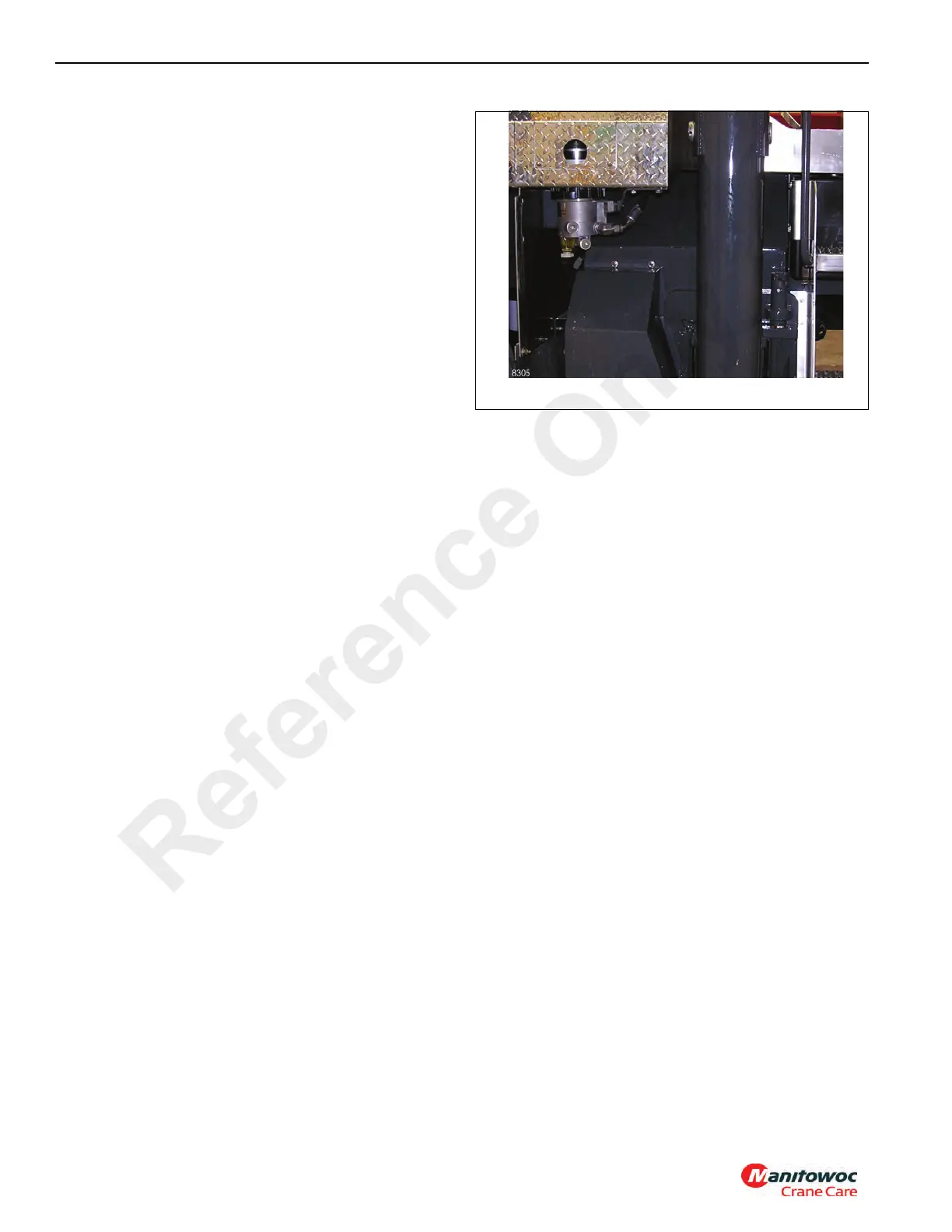
Fuel Filter-Water Separator
The fuel filter-water separator (see Figure 7-3) removes
impurities from the fuel and also removes water from the fuel
before it reaches the engine. It is mounted above the left
front outrigger box.
The fuel mixture passes through the outer wrap of the first
stage of the filter paper, where large droplets of water,
removed from the fuel, are formed. The water droplets drain
into a void between the two paper elements and to a
reservoir in the bottom of the housing, where it can be
drained through a petcock.
As the filter becomes clogged the level of fuel will increase.
When the filter looks full of fuel the filter should be changed.
Maintenance
Fuel Tank
The fuel tank should be kept filled, especially overnight, to
reduce condensation to a minimum. Refer to the applicable
engine manual for the recommended schedule for draining
any water or sediment from the tank.
Removal
1. Place a suitable container under the fuel tank and drain
all fuel from the tank.
2. Tag and disconnect the two lines from the tank.
3. Disconnect the electrical leads from the fuel level sender
units.
4. Remove the hardware securing the tank in place and
using a suitable lifting device, remove the fuel tank.
5. If a new tank is to be installed, remove the two fittings,
the fuel quantity senders, and steps from the tank and
install them on the new tank.
Installation
1. Position the tank and install the hardware securing the
tank in place.
2. Connect the electrical leads to the fuel quantity sender
units.
Reference Only
 Loading...


