4-47
TMS800E SERVICE MANUAL BOOM
Published 01-29-2014, Control # 496-00
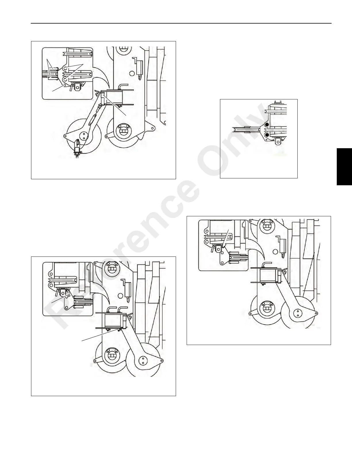
• Remove the retaining pins and take both pins (1) out of
the bearing points (2) at the front of the main boom head
Figure 4-66.
• Insert both pins into the holders (3) and secure them
with retaining pins.
• Release the retaining pin and remove the thin pin from
the bearing point (4).
• Rotate the auxiliary boom nose to the side of the main
boom head.
• Using the thin pin (1), fasten the auxiliary single-sheave
boom nose to the bearing point (2) Figure 4-67.
• Secure the pin with a retaining pin.
• The auxiliary single-sheave boom nose is now in
transport position.
Rigging in Working Position
On the left side of the main boom head, there is a holding
device. In working position, the auxiliary single-sheave boom
nose is attached to the main boom head at both bore holes
Figure 4-68.
• Release the retaining pin and remove the thin pin from
the bearing point Figure 4-69.
• Swing the auxiliary single-sheave boom nose in front of
the main boom head.
Reference Only
 Loading...


