ELECTRIC SYSTEM TMS800E SERVICE MANUAL
3-8
Published 01-29-2014, Control # 496-00
Relays
The carrier cab has 2 relays which are mounted on the cab's
power panel assembly located behind the operator's seat.
After removing the power panel's cover, relays K1 and K2
can be seen.
The description and function of these relays are listed on the
power panel's component identification decal as shown in
Figure 3-4.
Table 3-3
Carrier Fuse and Relays
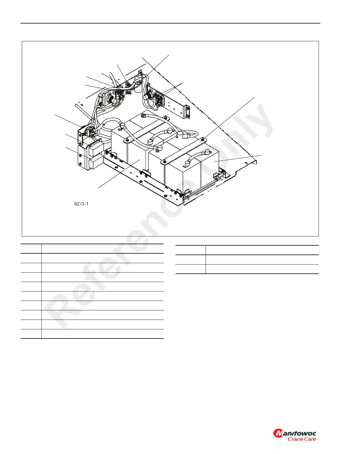
The carrier has 5 large ANL type fuses, (2) Fuse and Relay
Modules containing 14 ATO mini style fuses and 7 relays, all
located within the battery compartment as shown in Figure 3-
10.
Fuses
Fuses F301 through F305 are the large ANL style fuses used
to protect the batteries and large current carrying electrical
circuits.
F301 (100A) is energized regardless of the battery
disconnect switch and protects the electrical circuit supply
power to the engine, engine ECM, and the aftertreatment
components (if ISX engine is installed).
F302 (250A) is energized regardless of the battery
disconnect switch and protects the batteries and the
alternator charge circuit.
Item Description
1 Battery
2 Battery Disconnect Switch
3 100 Amp Fuse
4 Battery Hold Down
5 Power Relay
6 250 Amp Fuse
7 Battery Box Fuse and Relay Module #1
8 Battery Box Fuse and Relay Module #2
9 35 Amp Fuse
Relay Relay Assignment
K1 Wiper
K2 Heater Control Valve
Reference Only
 Loading...


