4-45
TMS800E SERVICE MANUAL BOOM
Published 01-29-2014, Control # 496-00
Traveling with Manually Offsettable Jib and/
or Inserts Erected
10 m (33 ft)/17 m (56 ft) Extension Plus 5 m (16 ft) or 10
m (32 ft) Inserts
Travel is permissible under the following conditions.
• The 10 m (33 ft) or 17 m (56 ft) jib shall be erected at
minimum offset.
• Jobsite travel only on firm, level surface.
• Main boom shall be fully retracted.
• Main boom angle: 0 degrees minimum, 40 degrees
maximum.
• Maximum travel speed: 4 km/h (2.5 mph).
• Counterweight shall be installed.
• The boom shall be over the front.
• Swing lock and pin shall be engaged.
• Hookblock must be removed from main boom nose.
• Headache ball may be reeved over jib, hanging 0.9 m (3
feet) below sheave.
• The tires shall be properly inflated.
AUXILIARY SINGLE-SHEAVE BOOM NOSE
(ADDITIONAL EQUIPMENT)
Identification
The auxiliary single-sheave boom nose is designed for the
crane it was delivered with.
If you wish to use the auxiliary single-sheave boom nose on
several Manitowoc/Grove cranes, it needs to be adapted to
the corresponding crane and marked with all the serial
numbers.
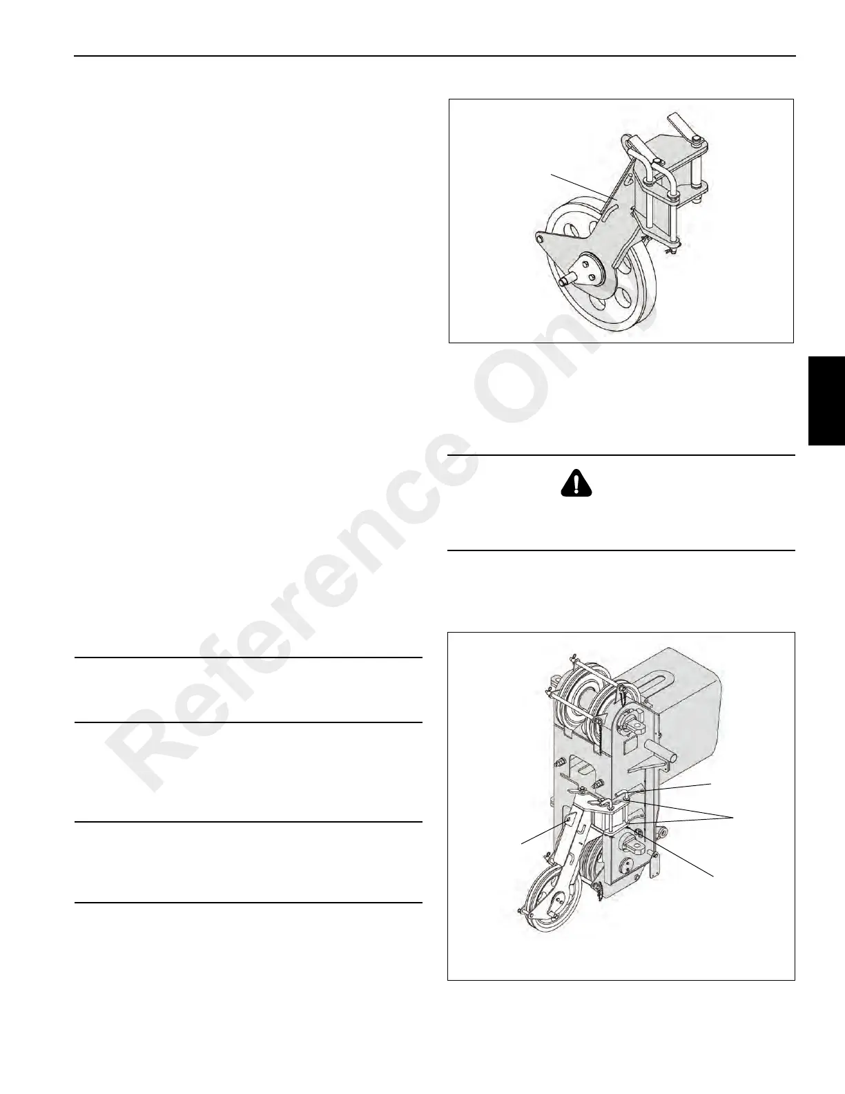
The serial number (1) is on a plate, in the front on the
auxiliary single-sheave boom nose Figure 4-61.
Installing/Removing Auxiliary Single-Sheave
Boom Nose
Installing Auxiliary Single-Sheave Boom Nose
• Loosen the retaining pin (4) and remove the pins (1)
from the bearing point (2) Figure 4-62.
CAUTION
Operate the crane only with the auxiliary single-sheave
boom nose that has the identical serial number.
CAUTION
The auxiliary single-sheave boom nose should only be
adjusted by Manitowoc Crane Care at the particular
location.
DANGER
Risk of accidents if boom nose should fall off! During
installation and removal, always use the proper materials
with sufficient load bearing capacities.
Reference Only
 Loading...


