2-51
TMS800E SERVICE MANUAL HYDRAULIC SYSTEM
Published 01-29-2014, Control # 496-00
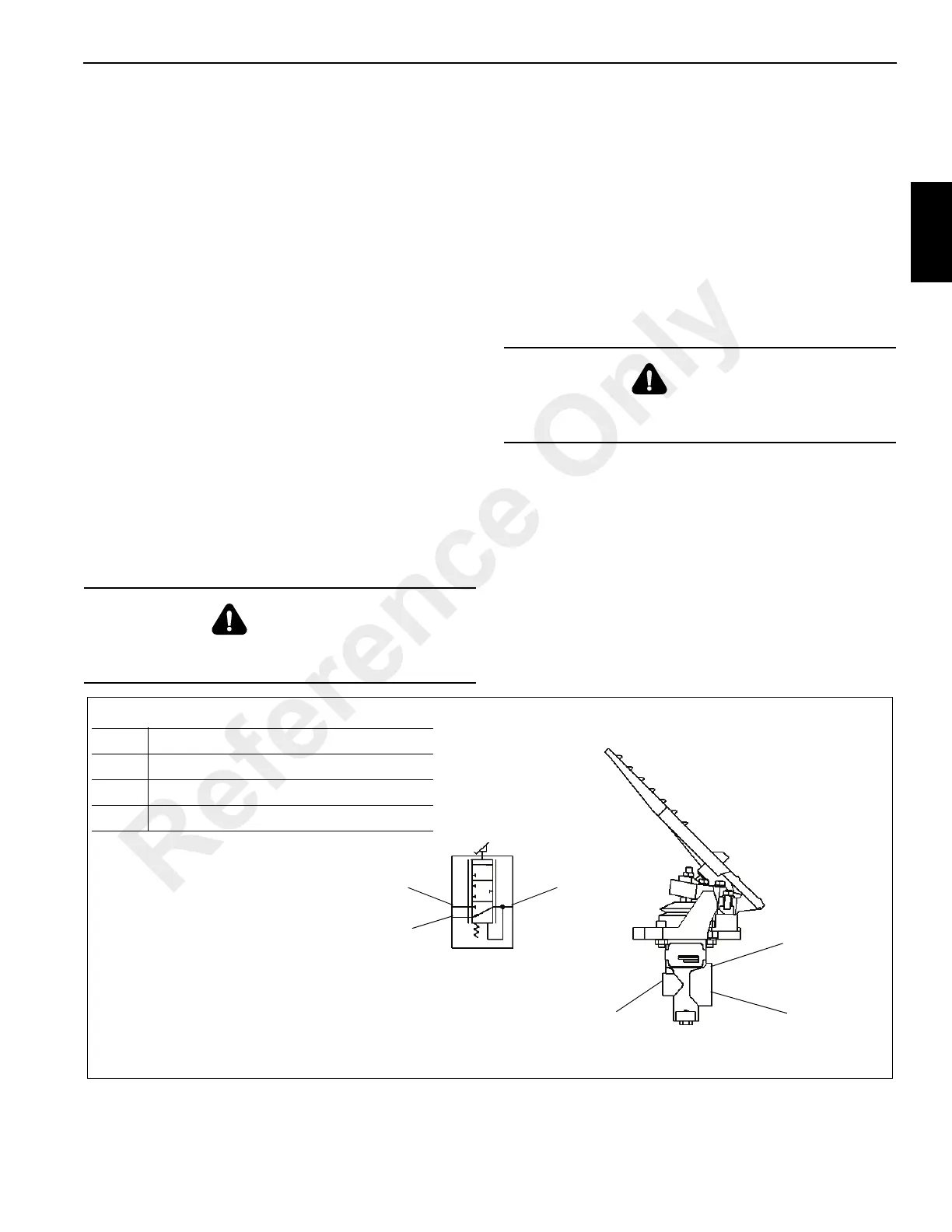
SWING POWER BRAKE VALVE
Description
The swing power brake valve (Figure 2-35) is used to
provide hydraulic pressure to the piston of the swing brake to
apply the brake. The valve receives its supply of oil from the
main directional control valve pilot generator port.
Depressing the brake pedal causes hydraulic oil to flow to
the top of the brake piston where, combined with spring
tension, the total force overcomes the brake release
pressure and applies the brake. When the valve is released,
excess hydraulic oil flows from the valve to the case drain
manifold and back to the reservoir.
Maintenance
Removal
1. Tag and disconnect hydraulic lines attached to the brake
valve. Cap or plug the lines and ports.
2. Remove the four bolts, lockwashers, flat washers, and
nuts which secure the brake valve to the cab floor.
Remove the brake valve.
Installation
1. Engage the swing lock.
2. Install the brake valve and secure in place with the four
bolts, flat washers, lockwashers, and nuts.
3. Attach the hydraulic lines to the brake valve as tagged
during removal.
Functional Check
1. Start the engine and let it idle.
2. Disengage the swing lock.
3. Slowly swing the turntable.
4. Test the valve by engaging the swing brake control valve
and operating the swing brake. Verify the swing brake
works when the pedal is pressed. Verify the brake is off
when the pedal is not pressed. Engage the swing lock
and make adjustments to the pedal as needed.
5. Check for leaks. Make repairs as needed.
DANGER
Engage the swing lock before installing the swing brake
valve.
DANGER
Engage the swing lock before adjusting the swing brake
valve.
1
2
3
1
2
3
FIGURE 2-35
6140
Item Description
1 Tank Port - To Case Drain Manifold
2 Pressure Port From Main valve
3 Regulated Output Port - To Swing Drive
Reference Only
 Loading...


