8-70
Published 01-29-2014, Control # 496-00
UNDERCARRIAGE TMS800E SERVICE MANUAL
3. Secure the hoses in place with the bolts, pipe clamps
and bolt inserts.
4. Install the shaft securing the rod end of the extension
cylinder to the outrigger beam.
5. Install the outrigger beam. Refer to Outrigger Beam
Installation in this section.
Functional Check
1. Activate the hydraulic system; extend and retract the
outrigger.
2. Observe the operation of the outrigger beam.
3. Check the hydraulic connections for any evidence of
leakage.
OUTRIGGER MONITORING SYSTEM
(OPTIONAL—STANDARD IN NORTH
AMERICA)
Description
The Outrigger Monitoring System (OMS) aids the operator in
accurately programming the Rated Capacity Limiter (RCL)
by automatically identifying the horizontal position of each
outrigger beam. The OMS uses eight sensors, two per
outrigger beam, to identify when an outrigger beam is
positioned to one of three pre-defined locations, including
fully retracted, mid-extend, and fully extended.
If the crane is setup on outriggers and “On Outriggers” is
chosen when programming the RCL, then the OMS indicates
to the RCL the horizontal position of each of the four
outrigger beams. Based on this information, the RCL will
choose the most conservative outrigger beam configuration
(that is, If three outriggers are fully extended and one is
retracted, the RCL will select retracted as the outrigger
configuration). A confirmation of this outrigger configuration
is all that is needed. Refer to the Rated Capacity Limiter
Operator’s Handbook for detailed instructions.
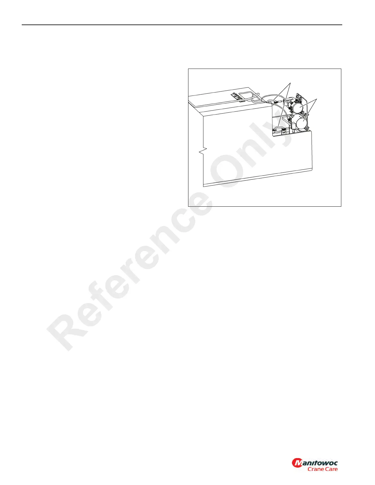
Removal
1. Extend the outrigger beam slightly for improved access
and shut down the engine.
2. Remove the outer access cover plate from outrigger
box.
3. Remove the OMS string potentiometer connector (1,
Figure 8-76) from the attaching point on the outrigger
beam.
NOTE: Avoid free-release of cable to prevent damage to
OMS string potentiometer (2).
4. Disconnect electrical harness connector and secure to
avoid damage.
5. Remove the mounting hardware.
6. Remove OMS string potentiometer from inside outrigger
beam.
Installation
1. Install string potentiometer inside outrigger beam.
2. Install the mounting hardware.
3. Attach the OMS string potentiometer connector to the
attaching point on the outrigger beam.
NOTE: Avoid free-release of cable to prevent damage to
the OMS string potentiometer.
4. Connect electrical harness connector to string potenti-
ometer.
5. Install access cover plate to outrigger box.
OUTRIGGER STABILIZER CYLINDER
Description
The stabilizer cylinders have 14.0 cm (5.50 in) diameter
bores and are the double-acting type. The cylinders are
pinned into tubes welded onto the end of the outrigger
beams. A port block is welded to the end of the cylinder rod
and a pilot-operated check valve is threaded into the port
block. Internal seals are used within the cylinder to prevent
internal and external leakage. A wiper ring is mounted to the
front of the cylinder barrel to wipe dirt from the rod as it is
retracted.
Each cylinder weighs approximately 90.2 kg (198.8 lb).
Reference Only
 Loading...


