2-39
TMS800E SERVICE MANUAL HYDRAULIC SYSTEM
Published 01-29-2014, Control # 496-00
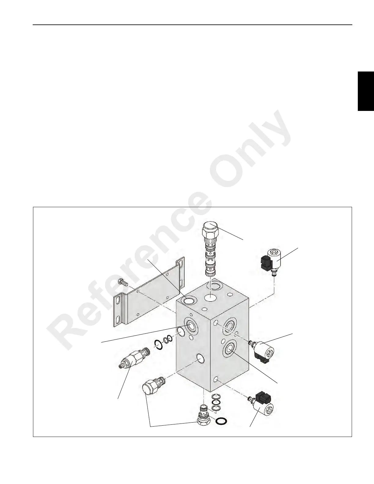
OUTRIGGER SELECTOR VALVE
Description
The outrigger selector valve (see Figure 2-25) directionally
controls the outrigger circuit. The valve is mounted on the
center of the carrier frame near the bearing. It receives pump
flow from the gear pump outlet of pump #2.
The valve contains a 214 bar (3100 psi) relief valve and a two
position two way solenoid valve that is normally open by
passing oil from the inlet port to the tank port. The valve also
contains a three position four way solenoid directional
control valve and 2 two-position, three way solenoid valves
that controls outrigger extend and retract.
Maintenance
Removal
1. Tag and disconnect the electrical connectors to the
outrigger selector valve.
2. Tag and disconnect the hydraulic lines to the outrigger
selector valve. Cap or plug the lines and ports.
3. Remove the bolts and washers securing the outrigger
selector valve to the crane. Remove the valve as a
complete assembly.
Installation
1. Attach the outrigger selector valve to the frame. Secure
the valve with the washers and bolts. Torque bolts, refer
to Fasteners and Torque Values, page 1-13.
2. Connect the hydraulic lines to the integrated outrigger
valve as tagged during removal.
3. Connect the electrical connectors to the integrated
outrigger valve as tagged during removal.
Functional Check
Cycle an outrigger cylinder several times. Verify the cylinder
extends and retracts properly.
12
10
3
6
5
9
11
7
8
FIGURE 2-25
6546-1
Reference Only
 Loading...


