8-28
Published 01-29-2014, Control # 496-00
UNDERCARRIAGE TMS800E SERVICE MANUAL
Camshaft Installation
1. Check the camshaft for cracks, wear and corrosion.
Check the cam head, bearing journals and splines.
Replace worn or damaged camshafts
2. Install new camshaft bushings and seals whenever you
install a new camshaft.
3. Tighten all spider bolts to the correct torque
(Figure 8-25).
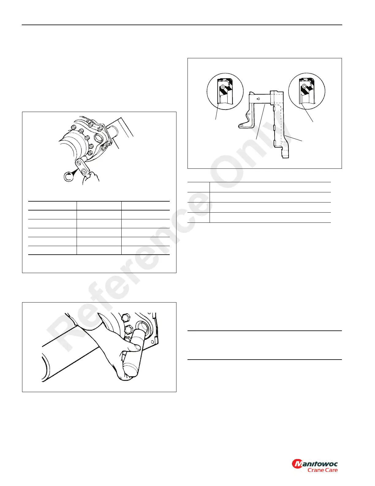
4. Use a seal driver to install new camshaft seals and new
bushings into the cast spider and camshaft bracket
(Figure 8-26).
NOTE: Install the seals with the seal lips toward the slack
adjuster to ensure grease purges at the slack end
(Figure 8-27).
5. If the camshaft bracket has been removed, install the
chamber bracket seal and bracket onto the spider.
Tighten the capscrews to the correct torque
(Figure 8-25).
REAR BRAKES
Description
The rear brakes are air actuated brakes which are cam
operated and that employ shoe and lining assemblies.
Automatic slack adjusters maintain the proper adjustment for
the push rod stroke and lining-to-drum clearance. The cam is
actuated by the air chamber.
Disassembly
1. Raise the crane on outriggers so that the rear wheels
are off the ground.
2. Place jack stands under the frame where the wheels are
to be removed. Support with safety stand.
3. Cage the spring brake with the caging bolt provided.
4. Fully release the slack adjuster so that the shoes retract
allowing the drums to clear the linings. Refer to Slack
Adjuster in this section.
5. Remove the brake drum.
FIGURE 8-25
Bolt Size Nm lb-ft
7/16” - 20 81 - 102 60 - 75
1/2” - 20 115 - 156 85 - 115
9/16” - 18 176 - 224 130 - 165
5/8” - 18 244 - 312 180 - 230
7/8” - 9 598 - 789 440 - 580
6599-4
Item Description
1 Seal Lip
2 Camshaft Bracket
3 Spider
CAUTION
Do not attempt to do any type of work under a crane that
is supported by only the outriggers or jacks.
Reference Only
 Loading...


