HYDRAULIC SYSTEM TMS800E SERVICE MANUAL
2-24
Published 01-29-2014, Control # 496-00
PRESSURE SETTING PROCEDURES
The following procedures should be used to properly check,
adjust and set the hydraulic system pressures.
The following equipment is required for checking the
hydraulic pressure settings.
• Pressure Gauge
• Three dial gauge 0-345 bar (0-5000 psi)
• Diagnostic quick disconnect - Grove P/N 9999101806
and straight adapter fitting 7447040401
• ORFS reducers as required to attach work port hoses to
the gauge.
NOTE: When checking the directional control valve relief
settings, unless otherwise specified, start with the
engine at idle RPM and move the controller to its
fully stroked position. Then slowly accelerate the
engine to the specified RPM. Read gauge and
make adjustments to specified setting.
When checking the outrigger relief valve setting,
start with the engine at idle RPM and activate and
hold the extend or retract switch. Then slowly
accelerate the engine to the specified RPM. Read
gauge and make adjustment as required.
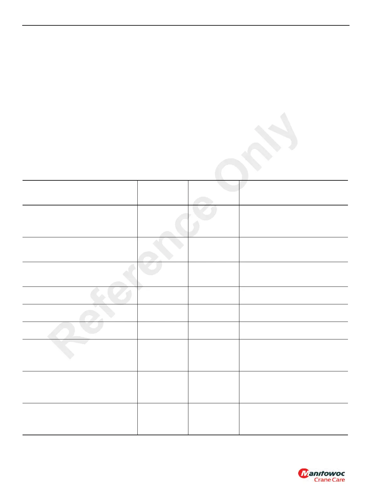
Table 2-2
Valve Pressure Setting Table
Reservoir Oil Temperature to be Approximately 49°C (120°F
Valve To Be Set
Pressure
Setting
bar (PSI)
Tolerance
bar (PSI)
Gauge Port (GPX) and Adjustment
Location
Hoist(s), and Lift Pressure Setting
276 (4000) ± 4 (50) GP2 Superstructure mounted
accessory manifold with swing
directional control valve (see
Figure 2-14)
Telescope Extend Pressure 179 (2600) ± 4 (50) GP5 Superstructure mounted main
directional control valve port relief
valve (see Figure 2-15)
Telescope Retract Pressure 239 (3460) ± 4 (50) GP5 Superstructure mounted main
directional control valve port relief
valve (see Figure 2-15)
Outrigger Extend/Retract and Swing Left/
Right Pressure Setting
214 (1500) ± 4 (50) GP7 Carrier mounted outrigger control
manifold (see Figure 2-18)
Air Conditioning Circuit Relief Valve
Pressure
103 (2000) ± 4 (50) GP Carrier mounted flow control
manifold (see Figure 2-17)
Steer Pressure Setting 150 (2175) ± 4 (50) GP8 Carrier mounted Priority Flow
Pump Relief (see Figure 2-19)
Swing Brake Supply Pressure Setting 18 - 20
(260 - 300)
See Range GP4 Superstructure mounted
accessory manifold with swing
directional control valve (see
Figure 2-14)
Pilot Supply Pressure Setting 28 - 31
(400 - 450)
See Range GP3 Superstructure mounted
accessory manifold with swing
directional control valve (see
Figure 2-14)
Counterweight Removal Extend/Retract
and Cab Tilt Relief Pressure Setting
172 (2500) ± 4 (50) GP2 Superstructure mounted
accessory manifold with swing
directional control valve (see
Figure 2-14)
Reference Only
 Loading...


