8-71
TMS800E SERVICE MANUAL UNDERCARRIAGE
Published 01-29-2014, Control # 496-00
Maintenance
NOTE: Refer to Cylinders, page 2-54 for Disassembly and
Assembly of the cylinders.
Removal
1. Extend the outrigger beam slightly for improved access
to the stabilizer cylinder. Shut down the engine.
2. Tag and disconnect the hydraulic hoses from the
stabilizer cylinder.
3. Remove the cylinder cap.
4. Place a jack capable of supporting the weight of the
stabilizer cylinder at the base of the cylinder barrel. Jack
up the cylinder just enough to relieve any pressure on
the cylinder retaining pin.
5. Remove the cotter pins securing the cylinder retaining
pin and remove the cylinder retaining pin.
6. Jack the stabilizer cylinder up just enough to insert the
retaining pin back into the cylinder. Insert the retaining
pin into the lugs on the cylinder and secure in place with
the cotter pins.
7. Fasten a nylon strap onto the cylinder retaining pin and
use an adequate lifting device to lift the stabilizer
cylinder out of the tube on the beam assembly.
Installation
1. Place a jack beneath the cylinder tube on the outrigger
beam. Using the same method as described under
Removal, lower the stabilizer cylinder into the cylinder
tube on the outrigger beam until the retaining pin is just
above the tube. Position the jack so that it will support
the cylinder in this position. Remove the lifting device
from the cylinder.
2. Remove the retaining pin and cotter pins from the
cylinder.
3. Lower the jack until the holes in the cylinder rod align
with the holes in the outrigger beam. Secure the cylinder
in place with the retaining pin and cotter pins.
4. Install the cylinder cap.
5. Connect the hydraulic hoses to the stabilizer cylinder as
marked during disassembly.
NOTE: Keep hydraulic fittings and hoses close to angles
shown in Figure 8-77 for proper tracking during
extension and retraction.
Functional Check
1. Activate the hydraulic system.
2. Extend and retract the stabilizer cylinder.
3. Check for smooth operation of the cylinder.
4. Check all hydraulic connections and hoses for evidence
of leakage.
CAUTION
Use a nylon strap to remove the cylinder. This will ensure
the retaining pin is not damaged.
CAUTION
Make sure that the piston side of all outrigger cylinders
are connected to the solenoid valve bank. Reversal of
port connection of the rod and piston sides could result in
severe damage to the cylinders as very high pressure
intensification will occur.
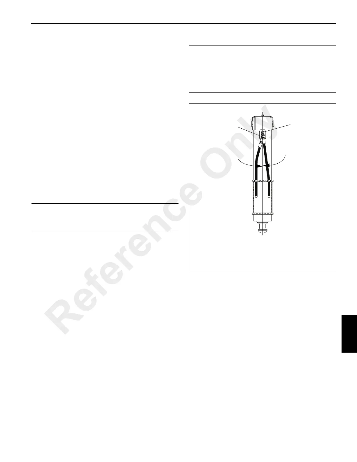
NOTE: Keep hydraulic fittings and hoses close to
angles shown for proper tracking during
extension and retraction.
Extend Port
Retract Port
FIGURE 8-77
15°
15°
Reference Only
 Loading...


