6-21
TMS800E SERVICE MANUAL SWING SYSTEM
Published 01-29-2014, Control # 496-00
Maintenance
Removal
1. Perform steps 1 through 4 of HYDRAULIC SWIVEL -
REMOVAL in this section.
2. Disconnect the batteries. (Refer to Electric System,
page 3-1.
3. Locate the connectors which join the collector ring
harness to the receptacles for the carrier.
4. Tag the connectors and their receptacles with numbers.
Disconnect the connectors from the chassis wiring
receptacles.
5. Disconnect the yellow ground wire from the weld stud on
the carrier frame.
6. Remove the clamp securing the wiring harness to the
retainer plate on the bottom of the hydraulic swivel
assembly.
7. Secure the wires from step 4 together so the harness
can be withdrawn through the center of the hydraulic
swivel.
8. Tag and disconnect the connectors from the receptacles
on the cab bulkhead mounting plate. Disconnect the
yellow ground wire from the weld stud on the
superstructure frame.
9. Remove the nuts and washers, and remove the cover
from the electrical swivel.
10. Loosen the setscrews securing the electrical swivel
mounting tube to the center post on the water swivel.
11. Remove the bolt and nut securing the electrical swivel
case to the bracket on the case of the water swivel.
12. Remove the swivel and wiring harness from the crane. If
necessary, remove the spacer bushing from the center
post.
Installation
1. If removed, install the spacer bushing on the center post.
Route the collector core wiring harness through the
center of the hydraulic and water swivels.
NOTE: The boom should be centered directly over the
front of the crane before adjustment is made to the
slew potentiometer.
2. Slide the electrical swivel mounting shaft onto the center
post.
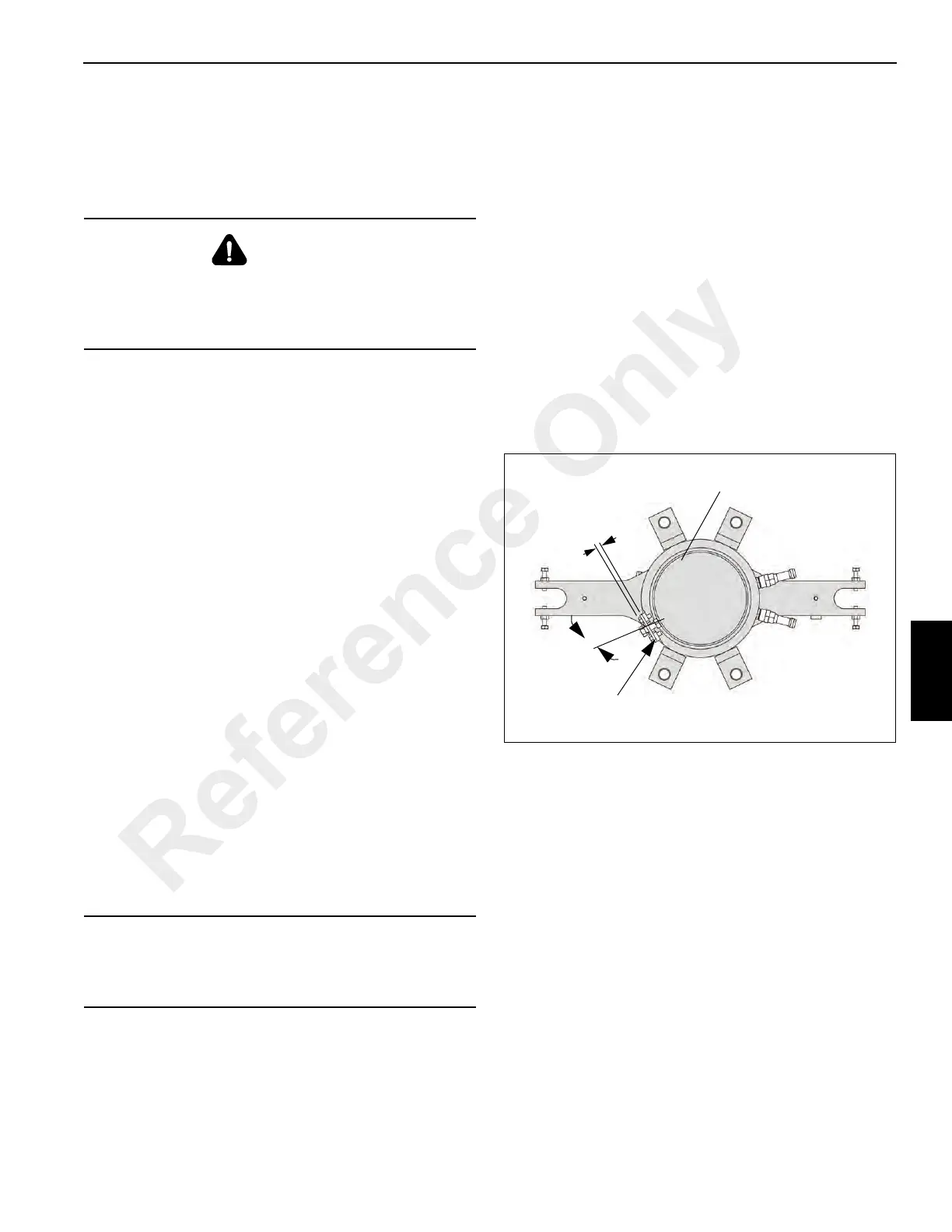
3. Ensure the threaded hole on the bottom of the electrical
swivel base is aligned with the mounting hole in the
bracket on the water swivel case. Install the bolt through
the hole in the bracket and install the nut. Screw the bolt
into the hole in the electrical swivel base until the bolt
head is approximately 6.4 mm (0.25 in) from the bracket.
Tighten the nut against the electrical swivel (see
Figure 6-7).
4. Apply Loctite® to the set screws securing the electrical
swivel to the center post and tighten them 5 to 6 Nm (45
to 55 lb-in).
5. Install the swivel cover and secure with two nuts and
washers.
6. Connect the wiring harness connectors to the
receptacles on the cab bulkhead mounting plate as
tagged during removal. Attach the yellow ground wire to
the weld stud inside the superstructure cab. Secure
ground wire with washer, lockwasher and nut
7. Unbundle the wires of the collector core wiring harness.
8. Plug the large flat connector into the carrier wiring
receptacle, connect red, black, and white wire
connectors and install the yellow ground wire to the weld
stud on the carrier frame. Secure the yellow ground wire
using a washer, lockwasher, and nut.
9. Install the clamp securing the harness to the retainer
plate on the bottom of the hydraulic swivel assembly.
DANGER
Disconnect the batteries before performing any
maintenance on the electrical system. Serious burns may
result from accidental shorting or grounding of live
circuits.
CAUTION
When withdrawing the wiring harness through the center
of the hydraulic and water swivels, ensure the wires do
not get caught and damaged.
30°
Plate
FIGURE 6-7
6 mm
6490-3
Top Of Swivel
Reference Only
 Loading...


