4-46
Published 01-29-2014, Control # 496-00
BOOM TMS800E SERVICE MANUAL
• Use an auxiliary crane to couple the holding device to
the connection eyes (3) on the auxiliary boom nose and
lift it to the left onto the main boom head.
• Align the auxiliary single-sheave boom nose so that the
bearing point (2) lines up to the front bore holes in the
holding device.
• Secure the auxiliary single-sheave boom nose to the
holding device using a pin (1).
• Secure the pin (1) with a retaining pin (4).
• Depending on the application, bring the auxiliary single-
sheave boom nose into transport position or working
position.
Removing the Auxiliary Single-Sheave
Boom Nose
• Attach an auxiliary crane to the connection eyes of the
boom nose.
In the working position, the auxiliary single-sheave boom
nose is positioned in front of the main boom head and is
fastened with three pins (1) Figure 4-63.
• Remove the retaining pins and draw all the pins out of
the bores and bearing points.
In the transport position, the auxiliary single-sheave boom
nose is positioned to the side of the main boom head and is
fastened with two pins.
• Remove the retaining pins and draw all the pins out of
the bores and bearing points.
• In the transport position, the auxiliary single-sheave
boom nose is positioned to the side of the main boom
head and is fastened with two pins.
• Lift the auxiliary single-sheave boom nose from the head
of the main boom.
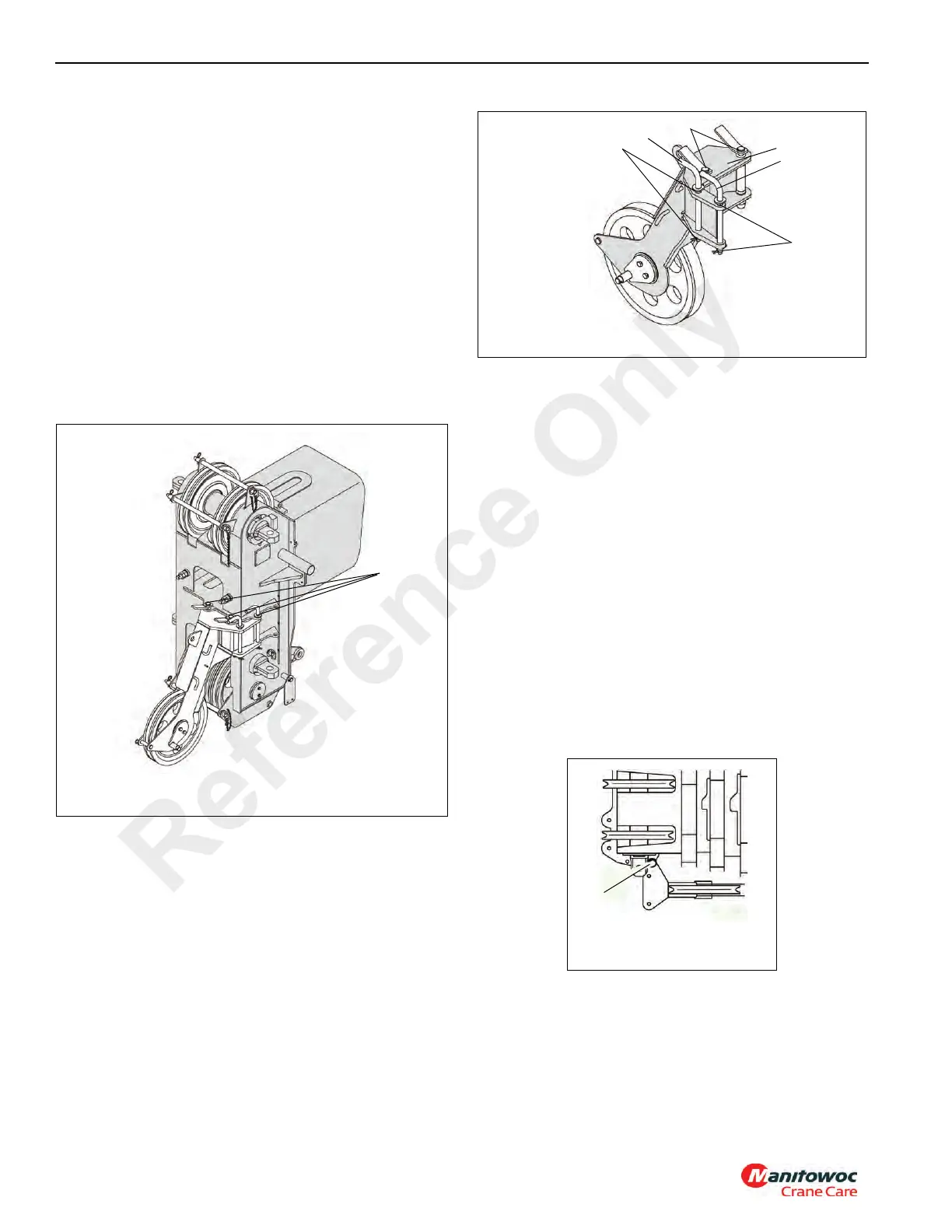
• Insert the two thin pins (1) and (3) into the bearing points
(2) and (4) on the auxiliary single-sheave boom nose
Figure 4-64.
• Insert the two pins (5) into the mounting brackets (6) in
front on the auxiliary single-sheave boom nose.
• Secure all pins using retainer pins.
RIGGING THE AUXILIARY SINGLE-SHEAVE
BOOM NOSE
Rigging in Transport Position
On the left side of the main boom head there is a holding
device. In transport position, the boom nose is connected to
the rear bore holes on the holding device, Figure 4-65.
Reference Only
 Loading...


