8-39
TMS800E SERVICE MANUAL UNDERCARRIAGE
Published 01-29-2014, Control # 496-00
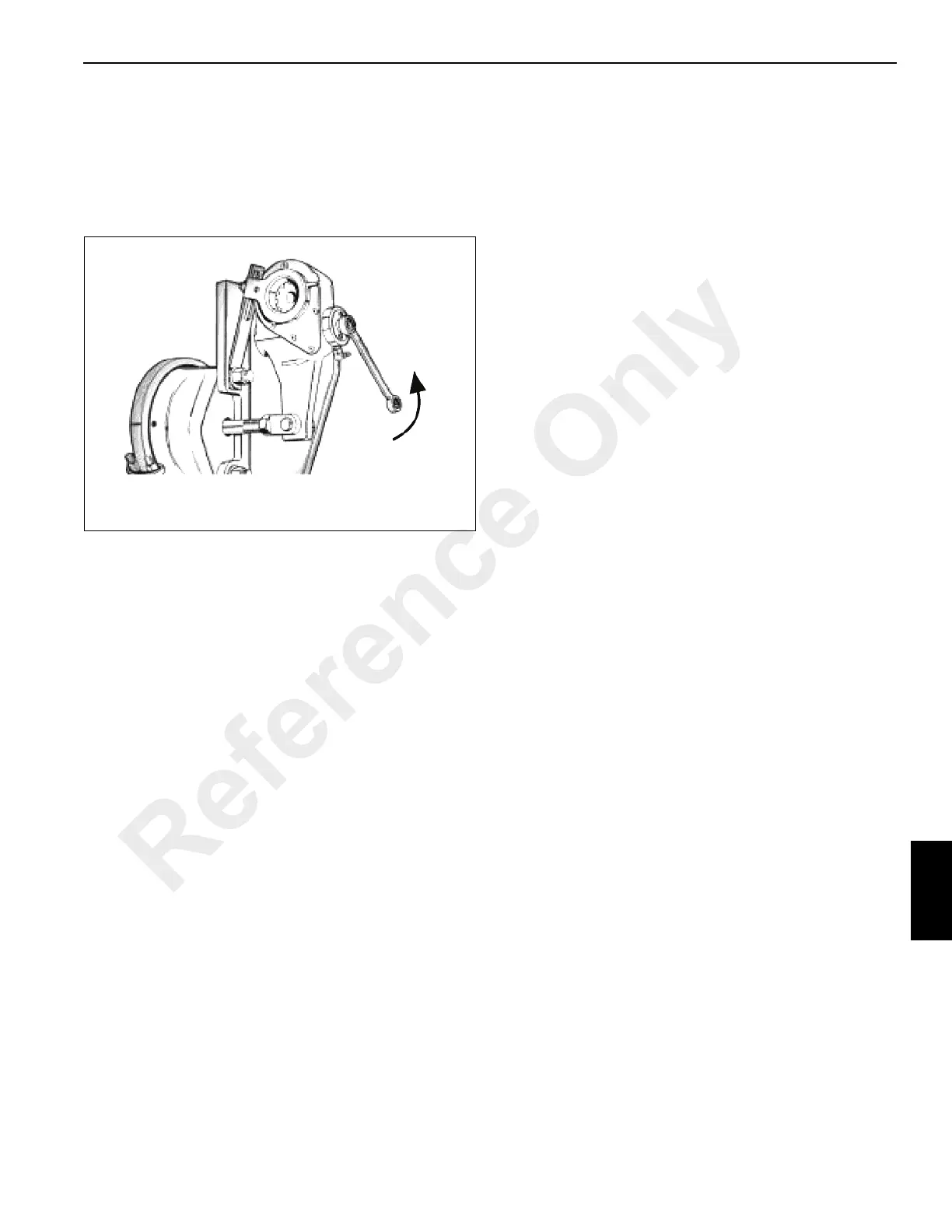
7. Rotate the adjusting hex approximately 1/8 turn in the
direction required and re-measure the stroke. Continue
this process until the stroke is within limits. A minimum of
17.6 Nm (13 lb ft) of torque is required to turn the hex
and overcome the internal clutch. A ratcheting noise will
be heard. Do not use an impact wrench or internal
damage will occur (Figure 8-50).
8. With brakes released, check installation indicator
(Figure 8-49) and (Figure 8-50) to determine proper
adjustment.
9. If installation indicator is not positioned properly, refer to
(Figure 8-50). Loosen fastener holding indicator to
anchor bracket, rotate indicator as required and
retighten fastener.
10. Uncage spring brake if so equipped.
AUTOMATIC SLACK ADJUSTER (REAR)
Description
The automatic slack adjuster (see Figure 8-51)
compensates for normal wear in the brake shoe linings by
maintaining a nominal clearance between the lining and
drum. These are preset at the manufacturer’s factory.
When the brake is applied the slack adjuster’s rotation
moves the shoes and linings into contact with the brake
drum. This movement also lifts the actuation rod through a
pre-set, free travel dimension that is normal lining to drum
clearance. Continuing the brake application rotates a one-
way clutch in its over riding mode, and at the same time
causes the large coil spring to deflect at a specific force. This
spring deflection allows the worm to move axially. The clutch
movement is restricted by a machine step. This movement
fully disengages the drive clutch from the worm and prevents
unwanted brake adjustment from occurring.
When the brake is released, the large coil spring resumes its
original load and position, which allows the drive clutch to re-
engage. Simultaneous to drive clutch re-engagement, if any
lining wear has occurred, the actuation rod rotates the one
way adjuster clutch an amount proportional to lining wear.
This motion rotates the worm, worm wheel, and the S-cam
shaft resulting in adjustment of the brakes.
Reference Only
 Loading...


