4-25
TMS800E SERVICE MANUAL BOOM
Published 01-29-2014, Control # 496-00
INSTALLING THE BI-FOLD MANUAL JIB
1. Before installing the jib make sure the crane is set up on
outriggers using normal setup procedures. Refer to
Section 3 - OPERATING CONTROLS and
PROCEDURES, in the Operator Manual.
NOTE: An auxiliary crane with sling is required to install
the bi-fold jib.
2. Check the transport condition of the bi-fold extension.
3. Using an auxiliary crane, attach sling to the bi-fold
extension.
4. Lift the bi-fold extension in front of the main boom with
the auxiliary crane and lock the 33 ft (10 m) section to
the right of the main boom head Figure 4-4.
5. Pin the left side to the boom nose.
6. Establish electrical connection between the extension
and the main boom.
7. For units equipped with hydraulic luffing jib, establish
hydraulic connections between the extension and the
main boom.
NOTE: You can also install the bi-fold swingaway jib in
front of a 16 ft (5 m) section when you are changing
directly from the 56 ft (17 m) bi-fold swingaway
extension to a jib.
Checking the Transport Condition
For transportation you must establish certain connections
between both parts of the lattice extension. The connections
which need to be established depend on whether the lattice
extension:
- is folded up at the side of the main boom for
transportation or
- is completely removed for transportation.
You must check transport condition:
- After stowing the lattice extension, before you drive
the crane with the lattice extension folded at the side
or work with the main boom.
- Before installation and before erecting the lattice
extension.
Transport condition with lattice extension folded at
the side
The transport condition with the lattice extension folded at
the side is created when all of the following connections are
established.
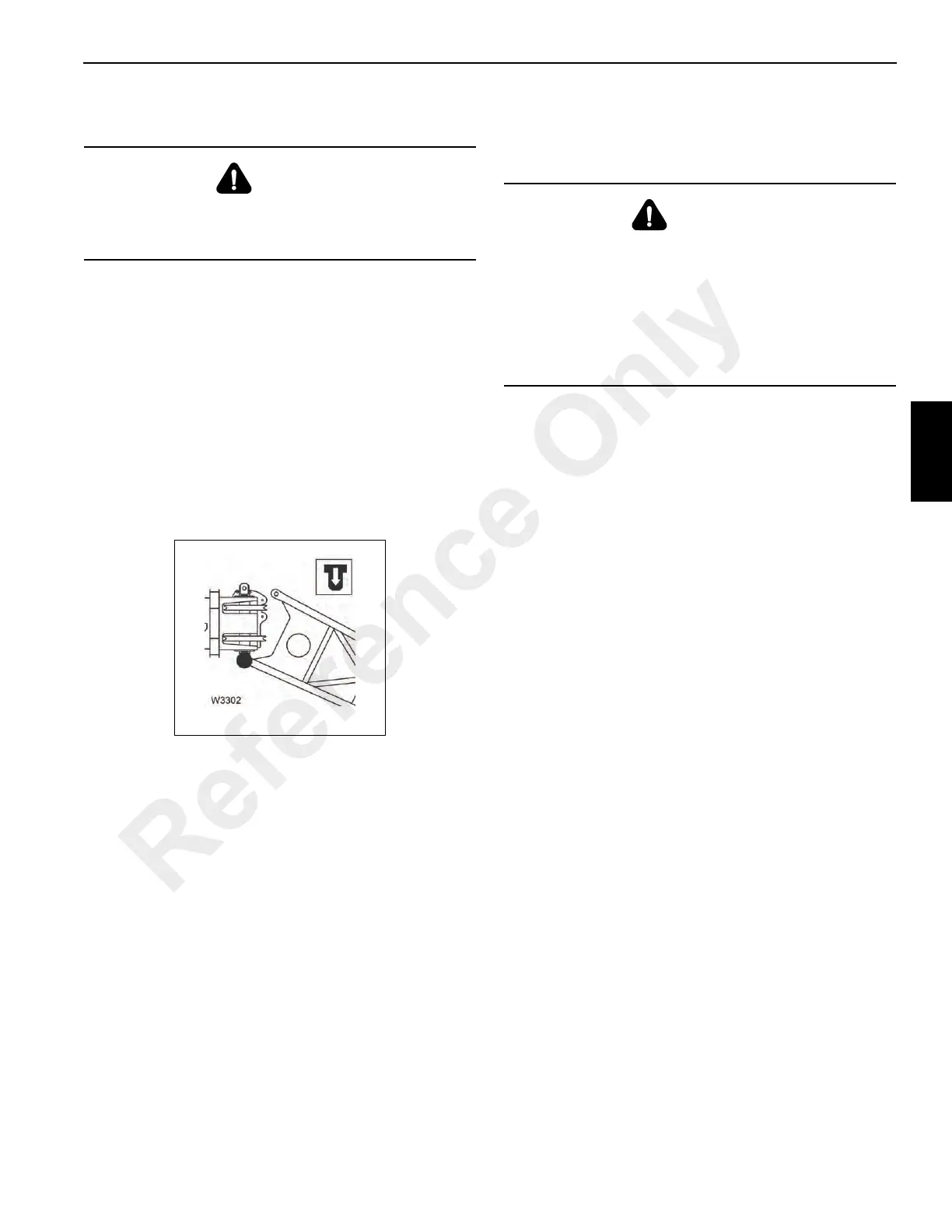
• Check the connections and establish them if
necessary Figure 4-5.
If 7 m (23 ft) section and 10 m (33 ft) section are folded
at the side
- The 10 m (33 ft) section is locked at the front mount
(2) on the main boom (Figure 4-5).
- The pins (4) are inserted on the pivot point between
the 7 m (23 ft) section and the 10 m (33 ft) section
Figure 4-5.
- The connection (8) in the middle area is between
the 7 m (23 ft) section/10 m (33 ft) section
Figure 4-5.
- The connection (8) between 7 m (23 ft) section and
main boom in the rear area is established
Figure 4-5.
If the 7 m (23 ft) section only is folded at the side
- The connection (8) in the middle area is between
the 7 m (23 ft) section and the main boom
Figure 4-5.
- The connection (5) between the 7 m (23 ft) section
and the main boom in the rear area is established.
DANGER
To prevent serious injury or death, always wear personal
protective equipment; that is, a hard hat, eye protection,
gloves and metatarsal boots.
DANGER
Be careful not to damage the lattice extension and the
main boom. Always put the lattice extension into transport
condition when folded at the side or working with the main
boom. Only then is the lattice extension secured against
slipping. This way you prevent the partly fastened lattice
extension hitting the main boom or the individual
components of the lattice extension hitting each other and
becoming damaged.
Reference Only
 Loading...


