8-32
Published 01-29-2014, Control # 496-00
UNDERCARRIAGE TMS800E SERVICE MANUAL
This motion rotates the worm, worm wheel, and the S-cam
shaft resulting in adjustment of the brakes.
Maintenance
There are 2 different styles of slack adjusters used for this
brake system. It is necessary to determine style applicable to
this crane.
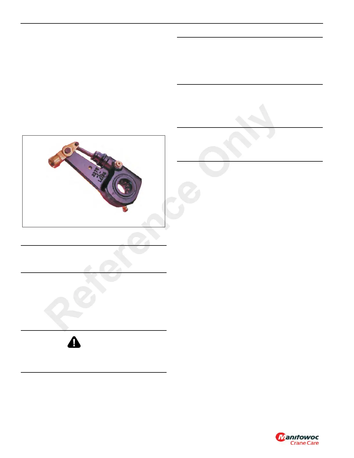
Slack Adjuster Style #1
NOTE: If your slack adjuster is as pictured in Figure 8-35
Style #1, use the removal, installation and
adjustment procedures that follows. See Slack
Adjuster Style #2, page 8-35.
Removal
1. Disengage the pull pawl. Use a screwdriver or
equivalent tool to pry the pull pawl at least 0.8 mm
(0.0313 in) to disengage the teeth from the actuator.
2. Use a wrench to turn the manual adjusting nut clockwise
until the brake shoes are fully retracted and the lining
clears the drum.
3. Remove both clevis pins and retainer clips or cotter pins.
4. Move the slack adjuster away from the clevis.
5. Discard the retainer clips and cotter pins and replace
them with new ones.
NOTE: Note the orientation of the slack adjuster with
reference to the push rod before removal to ensure
proper orientation at installation.
6. Remove the slack adjuster with a suitable puller.
Installation
1. Verify that the pushrod is fully retracted.
2. Install the inner washer on the camshaft. The inner
washer has a larger hole.
3. Apply Anti-Seize type lubricant to the camshaft splines.
Install the slack adjuster onto the camshaft with the
adjusting shaft hex pointing away from the air brake
chamber. Secure with outer shim washer(s) and snap
ring.
4. Rotate the adjusting shaft hex nut clockwise until the
slack adjuster arm and actuator rod holes line up with
the clevis holes.
5. Install the clevis pins and the cotter pins.
6. Adjust the brakes by turning the adjusting shaft hex
clockwise until the lining contacts the drum. Then rotate
the adjusting shaft hex counterclockwise 1/2 turn.
Adjustment Procedures
Brake Applied Stroke Measurement
Ensure that the brake applied stroke is within required values
as outlined below.
1. Chock the wheels.
2. Charge air tanks.
3. Release the parking brakes and shut down the engine.
CAUTION
You must disengage a pull pawl before rotating the
manual adjusting nut, or you will damage the pawl teeth.
CAUTION
When you remove a clevis pin that has a spring, hold the
spring with pliers. The spring can disengage from the
clevis with enough force to cause serious personal injury.
7092-9
FIGURE 8-35
Style #1
CAUTION
Always replace used clevis pin retainer clips with new
ones when you service an automatic slack adjuster. Do
not reuse retainer clips. When you remove a retainer clip,
it can bend out of shape and lose retention. Damage to
components can result.
CAUTION
Do not use a hammer to remove the slack adjuster.
Damage to the slack adjuster and/or camshaft splines
may result.
Reference Only
 Loading...


