6-23
TMS800E SERVICE MANUAL SWING SYSTEM
Published 01-29-2014, Control # 496-00
lock assembly completely out of the gear teeth when the foot
pedal is up. Verify the linkage can put the blade of the swing
lock assembly as far as possible between the gear teeth
when the foot pedal is down. Verify all attaching hardware is
secure and undamaged. Make adjustments as needed.
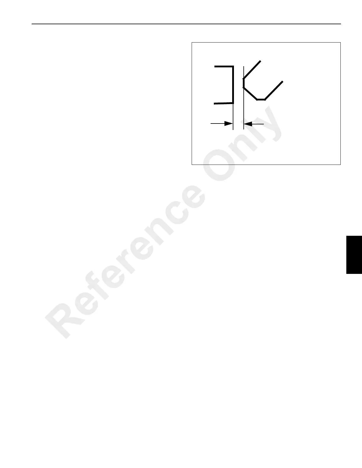
When the foot pedal is fully up, the top diagonal surface of
the blade of the swing lock assembly (the beveled surface
from the blade’s top horizontal surface to its “ax blade”
vertical surface should be 1.45 cm (0.57 in) from the tips of
the gear teeth.
If the swing lock assembly is damaged, install a replacement.
Align the blade of the swing lock assembly so it will fall
between gear teeth. Use the shim and the related attaching
hardware (two 5/16-18 screws and 5/16 inside diameter
lockwashers) to ensure the swing lock assembly cannot
move side to side, and can lock up the superstructure.
Torque the four 3/4-10 mounting bolts to their specified
torque found in Fasteners and Torque Values, page 1-13.
Gear Tooth
(typical)
Swing Lock
Assembly Blade
1.45 cm
(0.57 in)
FIGURE 6-8
7069
Reference Only
 Loading...


