8-10
Published 01-29-2014, Control # 496-00
UNDERCARRIAGE TMS800E SERVICE MANUAL
3. To ensure proper adjustment, drive the front wheels onto
greased plates or a suitable turntable so that the friction
between the tires and ground is reduced.
4. If greased plates are not available, raise the crane 3.75
cm (1.5 in) from the static height by lowering the
outrigger jack cylinders. This will allow adjustment of the
drag links without damage, but will require rechecking
the alignment after the axles are fully loaded
5. Crack the fittings on each steer cylinder and turn the
steering wheel from stop to stop, bleeding the cylinders
until there is no air. Tighten fittings.
6. Install the relay arm rig pins. Refer to Drag Link
Installation and Axle Synchronization in this section.
CAUTION
Do not attempt to adjust the axle drag links or the tie rod
ends while the full weight of the crane is on the axles
unless the tires are on greased plates or the crane is on
outriggers. Failure to do so may cause component
damage.
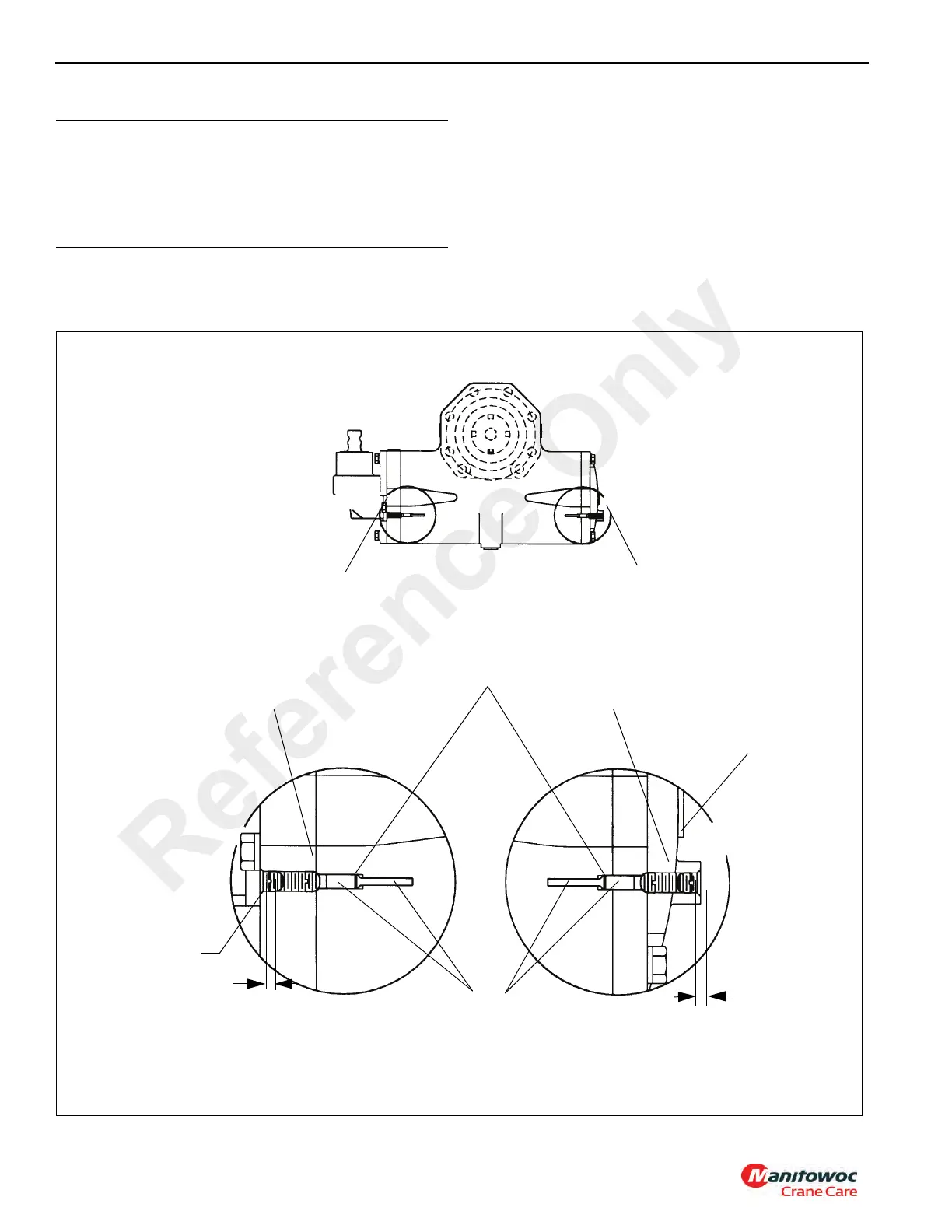
DETAIL A
DETAIL B
DETAIL A
DETAIL B
Rear plunger adjust on right hand turn.
Screw in to decrease travel; screw out to
increase travel.
Front plunger adjust on left hand turn.
Screw in to decrease travel; screw out to
increase travel.
Plunger
Plunger O-ring
Housing
Housing
Prior to gear installation, screw
plunger in until it bottoms out in
NOTE: Plunger(s) must not be screwed out beyond
this depth. Damage could result.
FIGURE 8-9
Prior to gear installation, screw
plunger in until it bottoms out in
4mm (0.16 in) min. acceptable
plunger head depth
4mm (0.16 in) min. acceptable
plunger head depth
Reference Only
 Loading...


