2-17
TMS800E SERVICE MANUAL HYDRAULIC SYSTEM
Published 01-29-2014, Control # 496-00
1. Remove carrier parts as needed to gain access to the
pump. It is bolted to the engine.
2. Tag the supply lines to the pump and tag the distribution
lines from the pump, then disconnect them. Cap or plug
the lines and ports.
3. Remove nut and lockwasher to free the No. 2 pump from
the pump support plate. As needed, loosen or remove
the 3/8-16 bolt and its washer to move or remove the
pump support plate.
4. Remove the bolts and washers attaching the No. 2 pump
to the drive pad on the engine. Remove the pump.
5. Discard the gasket. Clean the gasket compound and
any gasket residue from the engine drive pad and the
No. 2 pump.
6. Cover the drive pad’s opening to prevent dirt from
entering.
No. 2 Pump Inspection and Repair
Refer to the Shop Reference and Maintenance Guide for
repair instructions as applicable.
CAUTION
Keep the pump as level as possible to avoid damaging
the input spline.
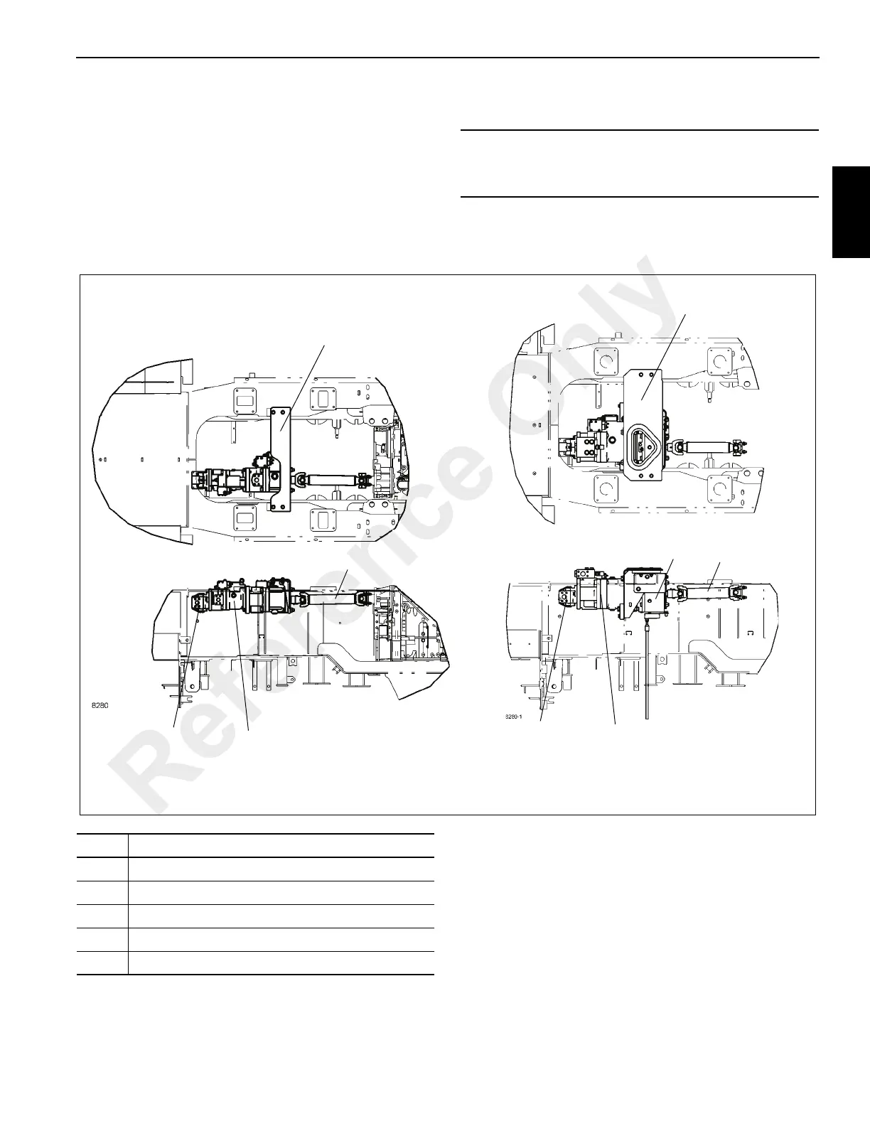
FIGURE 2-6
Right Side of Crane
2
3
4
5
1
QSM Pump Installation
4
3
2
1
ISX Pump Installation
Item Description
1 Pump No. 1 Piston Pump
2 Pump No. 1 Gear Pump
3 Support Bracket
4 Propeller Shaft (connects to engine)
5 Clutch (ISX only)
Reference Only
 Loading...


