1
1.2
1.3
INTRODUCTION
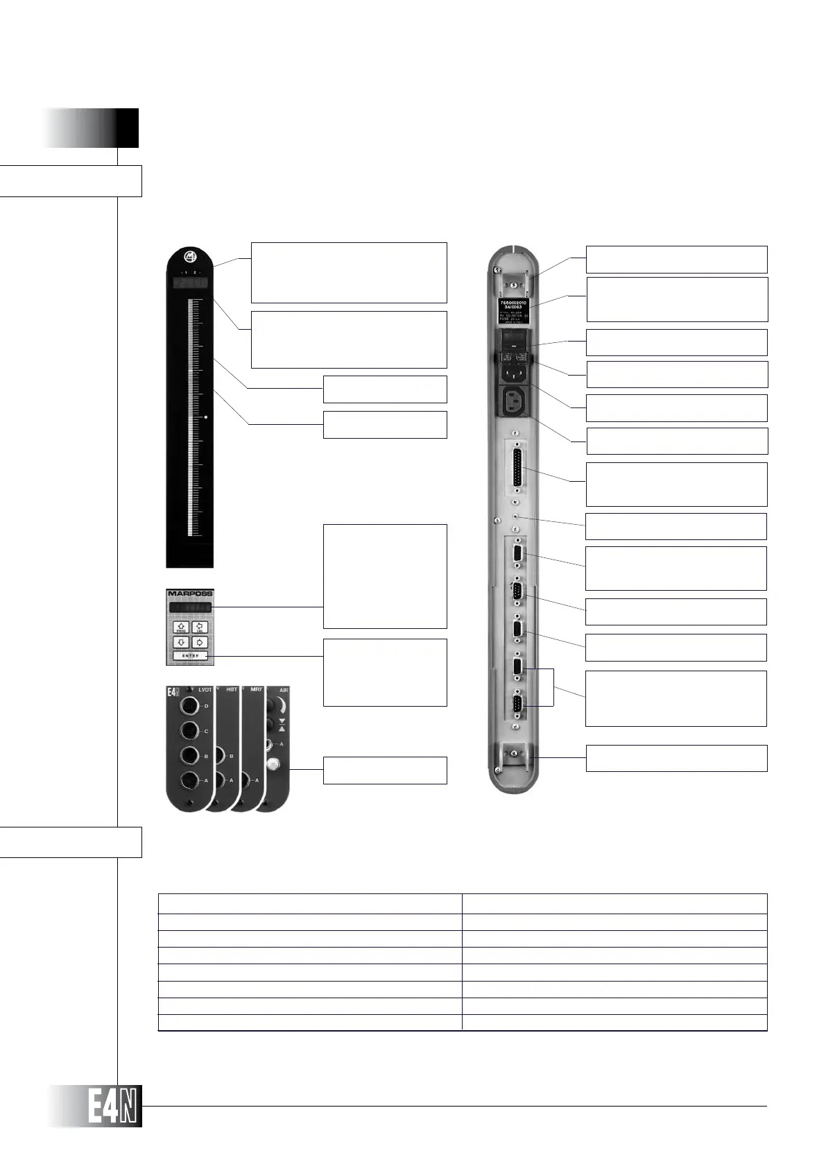
FRONT AND REAR VIEWS
Three-color scale
Tolerance limits
2 LED indicators:
4-digit display for
8-character alpha-
numeric display for:
-
rative measurements
Keypad for:
Transducer set-up
Transducer modules
Hook
Power supply switch
Plate showing serial number and
power supply specification
Power supply connector
Connector for power jumper cable
BCD relay output (optional)
Connector for external pushbut-
ton panel or footswitch
RS232C output
Analog/Digimatic output
Hook
TECHNICAL SPECIFICATIONS
Ground pin
Signal transfer bus
(Working only with sw
release V 2.72 or V 4.0)
85/265 VAC 50/60 Hz
40 VA
2A delayed
IP 50
-40/+60 °C
0/+50 °C
3.7 kg. approx.
po w e r s u p p l y
vo l t a g e vari ation
ma x i m u m c o n s u m p t i o n
Fu s e
De g r e e o F p r o t e c t i o n
st o r a g e t e m p e r a t u r e
op e r a t i n g t e m p e r a t u r e
we i g h t
(EMC)