65
5
5.2
PROG
CAL
ENTER
12
ADJUSTMENT PROCEDURE
To adjust air/electronic sensors you require two master gauges, a min. master and a max. master.
Example 1:
Inner diameter measurement with a pneumatic plug gauge.
Upper tolerance limit = 50.020 mm
Max master = 50.015 mm
Lower tolerance limit = 49.080 mm
Min. master = 49.082 mm
To adjust air/electronic sensors, start by adjusting the air supply pressure. Adjust using the
pressure regulator and gauge. The pressure setting must be in the range 1.5 bar (min.) to 4 bar (max.).
The ideal air supply pressure is 3 bar.
N.B.: Before performing the following procedures parameters K.CH. and SENS. must be programmed as:
K.CH. = -1.000
SENS. = +1.000
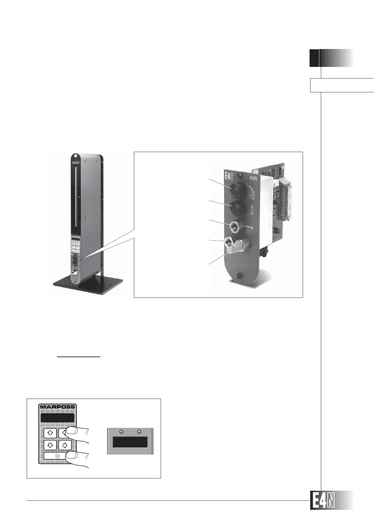
ADJUSTING AIR/ELECTRONIC SENSORS
Note: The sensitivity and zero adjusters of the air/electronic converter module are turned fully to the right to the
OFF position.
Step 1: Press the UP arrow key (CAL) and the
ENTER key together for two seconds.
The column will switch to the ADJUSTMENT
mode. The message "ADJ" will appear on
the alphanumeric display and the message
"ADJ0" will appear on the 7-segment
display.
A D J
Step 1
ADJ0
SENSITIVITY ADJUSTER
ZERO REGULATOR
AIR GAUGE CONNECTOR
AIR SUPPLY CONNECTOR
AIR SILENCER/EXHAUST