Chapter 4 EI system diagnosis Section 4 EI system troubleshooting
4—22
Is the input voltage OK?
YES
Go to Step 2.
NO
●
LooseorpoorcontactsontheECU
coupler.
●
OpenorshortcircuitintheO/Bwire
or G/Bl wire.
Step 2
1)
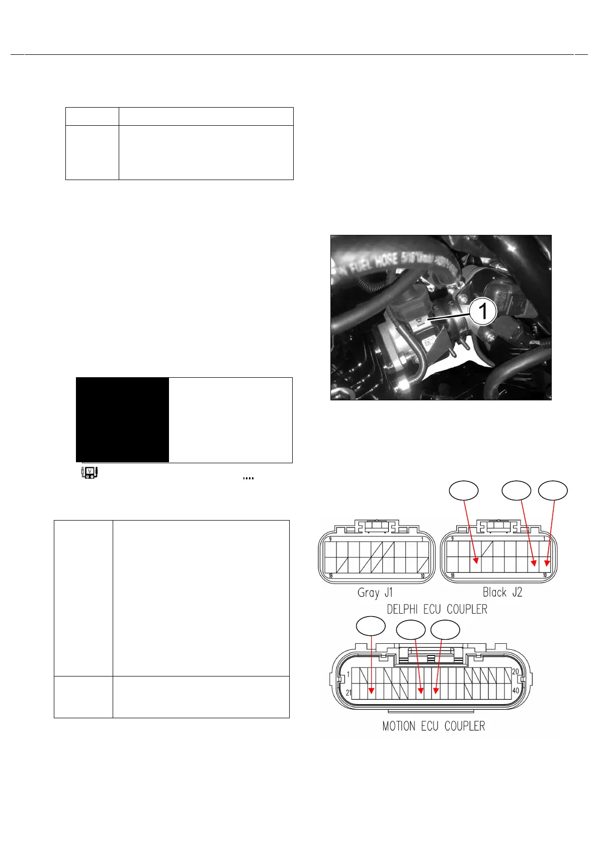
Connect the MAP & IAT Sensor coupler .①
2)
Inserttheneedlepointedprobestotheleadwire
coupler.
3)
Turn the ignition switch to the “ON”position.
4)
Measurethe MAP & IAT
Sensoroutputvoltageat thewire
sidecoupler(betweenBl/G
andG/Blwires).
Tester knob indication:Voltage(—)
Is the output voltage OK?
Approx. 1.5V at idle
speed
(
⊕
Bl/G-
⊖
G/Bl)
MP & IAT
Sensor out put
voltage
YES
●
O/B, Bl/G or G/Bl wire openor
shorted to ground, or poor B16
(J2-16) ,
B11(J2-11) or
B10(J2-10)connection of ECU
coupler.
●
If wire and connection are OK,
intermittent trouble or faulty
ECU.
●
Recheck each terminal and wire
harness for open circuit and
NO
If check result is not satisfactory,
replace the MAP & IAT Sensor
with a new one.
B16
B11
B10
B16
B11
B10
 Loading...