Chapter 6 Chassis section 5 Steering
6—23
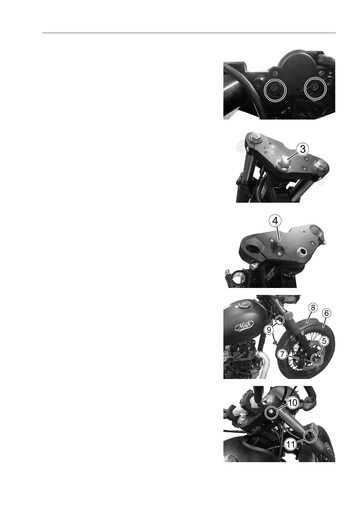
Remove ignition switch lock retaining bolts.
As Fig. 5.5.14.
Remove the ignition switch lock.
Remove the large cover nut③and the large washer.
As in Fig.5.5.15.
Tap the upper tray ④and remove it. As in
Fig.5.5.16
·
In order to facilitate the disassembly of the lower
bracket combination, it is necessary to use a jack or
wood block to raise the front wheel, remove and extract
the front axle , and⑤ remove the front wheel .⑥
Remove the brake calipers
Remove the front fender .⑧
Remove the speedometer soft axis clip from the ⑨
front right shock absorber assembly.
As in Fig.5.5.17.
Remove the front shock absorber assembly after
loosening the upper and lower clamping bolts and ⑩
of the front shock absorber.
Fig.5.5.14
Fig.5.5.15
Fig.5.5.16
Fig.5.5.17
Fig.5.5.18