CONTROL SYSTEM
07-40–23
07-40
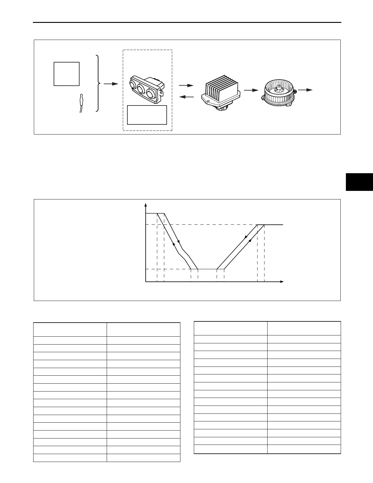
AIRFLOW VOLUME CONTROL SYSTEM DIAGRAM
id074000102500
End Of Sie
AIRFLOW VOLUME CONTROL OPERATION
id074000102600
Airflow Volume Automatic Control
• The front climate control unit calculates the applied voltage to the blower motor based on the input from the
target temperature, ECT sensor and evaporator temperature sensor (front/rear), and outputs the drive signal to
the power MOS FET (front/rear). However, the warm-up correction, mild start correction, MAX HOT and MAX
COLD correction and defroster correction take precedence under the operation conditions of the warm-up
correction, mild start correction, MAX HOT and MAX COLD correction and defroster correction.
• Switches the front blower motor applied voltage in 31 steps when the front power MOS FET is on. The front
blower motor applied voltage is as follows:
OUTPUT
FEEDBACK
POWER MOS FET
(FRONT/REAR)
OPERATION
BLOWER MOTOR
(FRONT/REAR)
AIRFLOW
VOLUME
CHANGE
TARGET
TEMPERATURE
ECT
SENSOR
EVAPORATOR
TEMPERATURE
SENSOR
(FRONT/REAR)
ENGINE
COOLANT
TEMPERATURE
SIGNAL
FRONT
CLIMATE
CONTROL
UNIT
ac9uun00000230
(V)
TARGET TEMPERATURE
°C {°F}
LO HI
BLOWER MOTOR
APPLIED VOLTAGE
am8rrn00000275
Fan level
Front blower motor
applied voltage
13.41 V
23.73 V
34.05 V
44.37 V
54.69 V
65.01 V
75.33 V
85.65 V
95.97 V
10 6.29 V
11 6.61 V
12 6.93 V
13 7.25 V
14 7.57 V
15 7.89 V
16 8.21 V
17 8.53 V
18 8.85 V
19 9.17 V
20 9.49 V
21 9.81 V
22 10.13 V
23 10.45 V
24 10.77 V
25 11.09 V
26 11.41 V
27 11.73 V
28 12.05 V
29 12.37 V
30 12.69 V
31 (MAX HI)
V
B
Fan level
Front blower motor
applied voltage
3423-1U-06H(07-40).fm 23 ページ 2006年11月22日 水曜日 午後2時48分