CONTROL SYSTEM
07-40–25
07-40
Airflow Volume Manual Control
• The blower motor applied voltage (airflow volume) can be switched in seven (front) / fifteen (rear) steps with the
fan switch.
Front
Rear
End Of Sie
NG: AIRFLOW MODE CONTROL
AIRFLOW MODE CONTROL OUTLINE
id074000102700
Features
• Consists of the airflow mode automatic and manual controls with the front climate control unit controlling the
airflow mode via the front airflow mode actuator or rear airflow mode actuator.
End Of Sie
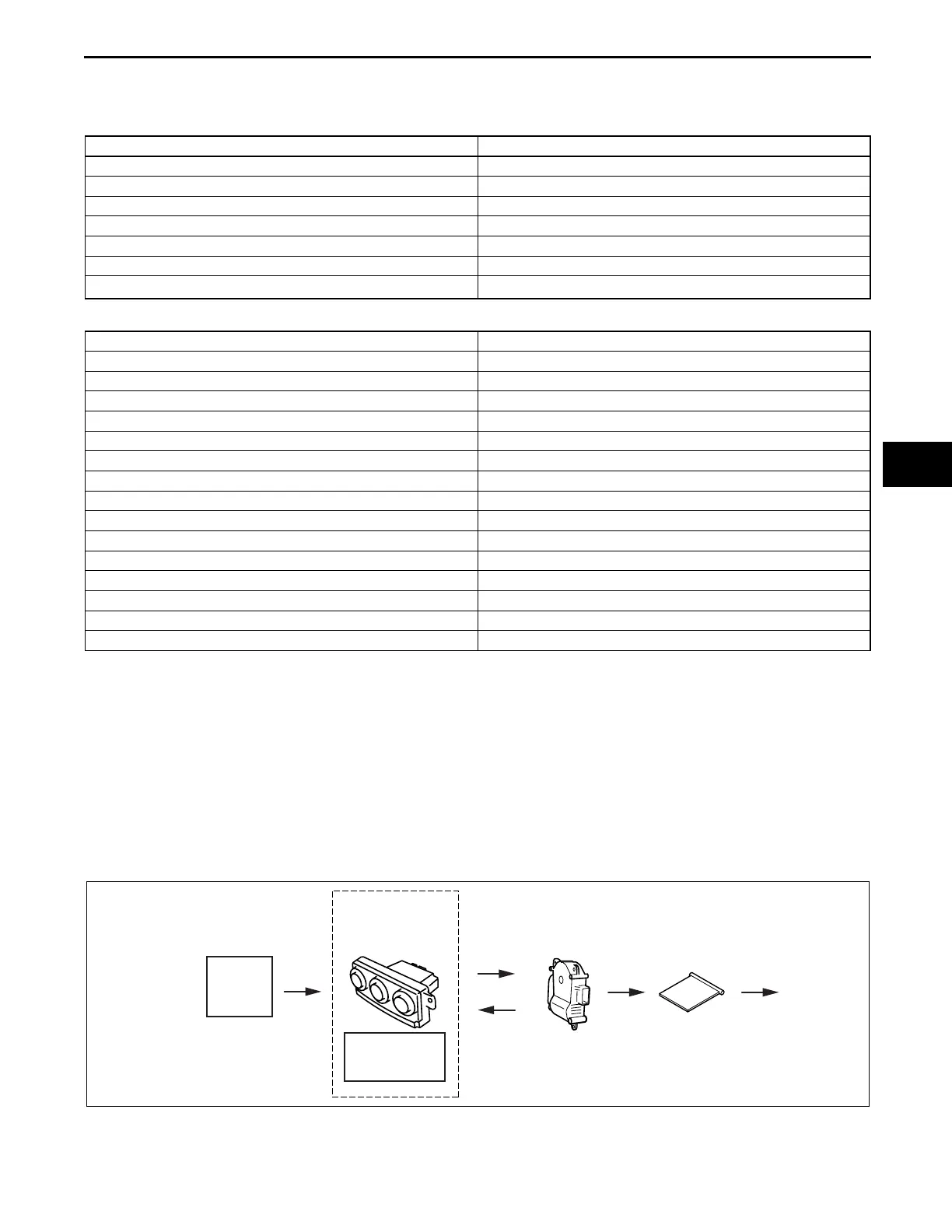
AIRFLOW MODE CONTROL SYSTEM DIAGRAM
id074000102800
End Of Sie
Fan switch Blower motor applied voltage
1st 3.41 V
2nd 5.01 V
3rd 6.61 V
4th 8.21 V
5th 9.81 V
6th 11.41 V
7th
V
B
Fan switch Blower motor applied voltage
1st 3.41 V
2nd 3.88 V
3rd 4.35 V
4th 4.82 V
5th 5.29 V
6th 5.76 V
7th 6.23 V
8th 6.70 V
9th 7.17 V
10th 7.64 V
11th 8.11 V
12th 8.58 V
13th 9.05 V
14th 9.52 V
15th 10.0 V
TARGET
TEMPERATURE
ECT
SENSOR
ENGINE
COOLANT
TEMPERATURE
SIGNAL
FRONT
CLIMATE
CONTROL
UNIT
OUTPUT
FEEDBACK
AIRFLOW MODE
ACTUATOR
(FRONT/REAR)
OPERATION
AIRFLOW
MODE
DOOR
AIRFLOW
MODE
CHANGE
ac9uun00000231
3423-1U-06H(07-40).fm 25 ページ 2006年11月22日 水曜日 午後2時48分