AUTOMATIC TRANSAXLE SHIFT MECHANISM
05-18–5
05-18
SHIFT-LOCK SYSTEM OPERATION
id051800100800
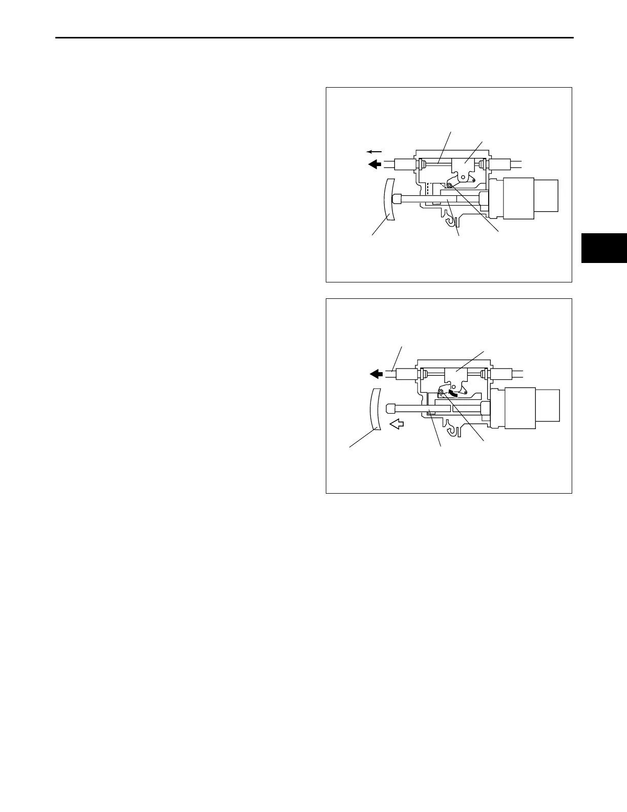
The selector lever can be shifted from P position only when the following conditions are satisfied.
• The brake pedal is depressed.
1. When the brake pedal is not depressed, the slider
pin is pressed into the position shown below by
the brake pedal. Thus the slider block is inhibited
from moving in direction A via the cam. In this
condition, the interlock cable and interlock cam
are locked, and the guide pin on the shift lever
does not move out of the position. Thus the select
lever cannot be shifted to other than P position.
2. When the brake pedal is depressed, the slider pin
moves freely in direction B. The slider block also
starts to move freely. The interlock cable and
interlock cam are not locked, thus shifting out of P
position becomes possible.
End Of Sie
NG: KEY INTERLOC K SYSTEM
KEY INTERLOCK SYSTEM OUTLINE
id051800100500
• The key interlock system, which is composed of the interlock cable and steering lock, prevents the ignition
switch from being removed when the selector lever is in any position other than the P range. (The ignition
switch cannot be turned to the LOCK position.)
End Of Sie
SLIDER PIN
CAM
INTERLOCK CABLE
SLIDER BLOCK
A
SELECTOR
LEVER SIDE
BRAKE PEDAL
acxuun00000641
SLIDER PIN
CAM
INTERLOCK CABLE
SLIDER BLOCK
B
SELECTOR
LEVER SIDE
BRAKE PEDAL
acxuun00000642
3423-1U-06H(05-18).fm 5 ページ 2006年11月21日 火曜日 午後5時20分