GLASS/WINDOWS/MIRRORS
09-12–13
09-12
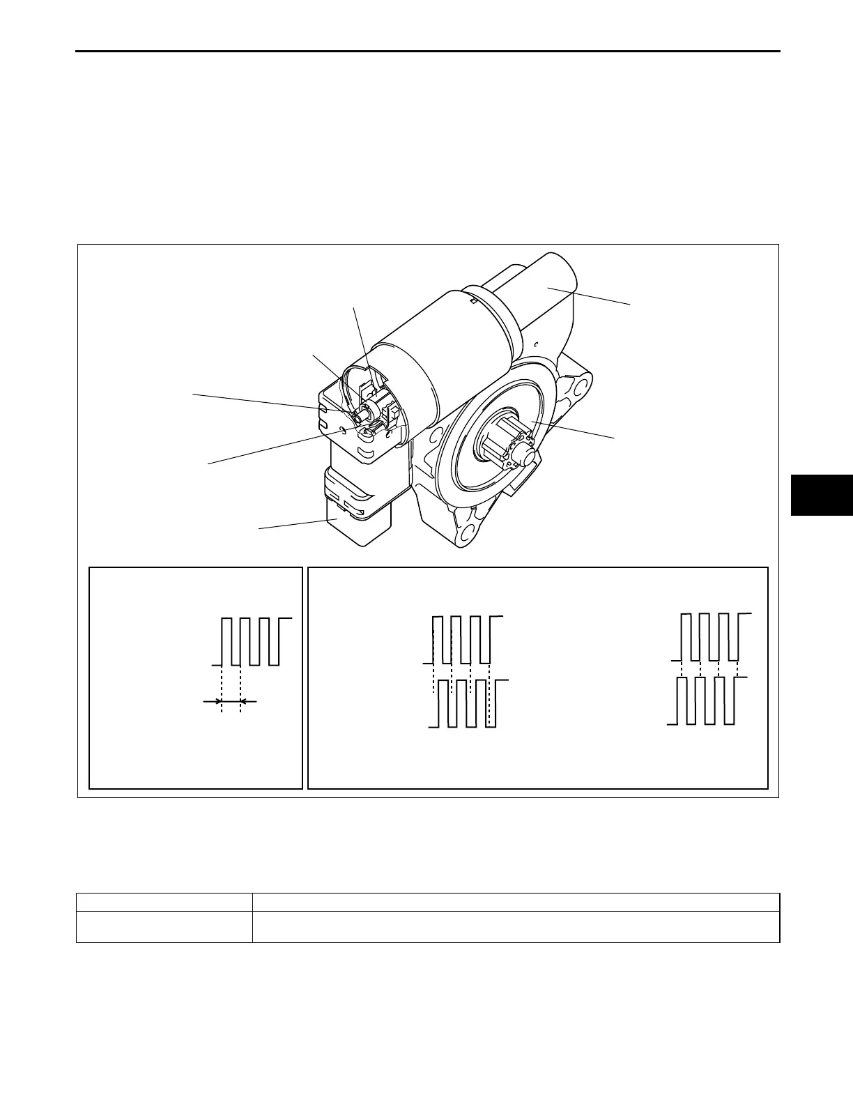
POWER WINDOW MOTOR CONSTRUCTION
id091200101400
• Consists of a motor, connector, and gear.
• Two Hall effect switches are located in the connector.
• The Hall effect switch utilizes magnets set on a rotating axis to detect the motor rotation, and outputs a
synchronized pulse to the power window main switch.
• Hall effect switch 1 outputs one pulse cycle for each rotation of the power window motor axle and the power
window main switch detects motor rotation speed from this.
• Hall effect switch 2 outputs pulse corresponding to motor rotation in the same manner as Hall effect switch 1.
The high and low pulse points of Hall effect switches 1 and 2 are different during opening and closing because
the phase difference shifts by 90°, allowing the power window main switch to detect the rotational direction of
the power window motor.
End Of Sie
NG: OUTER MIRROR
POWER OUTER MIRROR OUTLINE
id091200100700
End Of Sie
LO
HI
LO
HI
LO
HI
LO
HI
LO
HI
MOTOR
CONNECTOR
GEAR
HALL EFFECT SWITCH 1
HALL EFFECT SWITCH 2
SHAFT
MAGNET
PULSE 1
(HALL EFFECT
SWITCH 1)
PULSE 2
(HALL EFFECT
SWITCH 2)
PULSE 1
(HALL EFFECT
SWITCH 1)
PULSE 1
(HALL EFFECT
SWITCH 1)
PULSE 2
(HALL EFFECT
SWITCH 2)
ONE REVOLUTION
OF POWER WINDOW
MOTOR
UP
DOWN
WINDOW MOVEMENT
DISTANCE
WINDOW MOVEMENT
DIRECTION
acxuun00000401
Improved convenience • Power outer mirror (mirror glass adjusting function) adopted
Improved visibility • Heated outer mirror adopted (See 09-12-3 REAR WINDOW DEFROSTER SYSTEM
WIRING DIAGRAM.)
3423-1U-06H(09-12).fm 13 ページ 2006年11月21日 火曜日 午後5時37分