CHARGING SYSTEM [MZI-3.5]
01-17–2
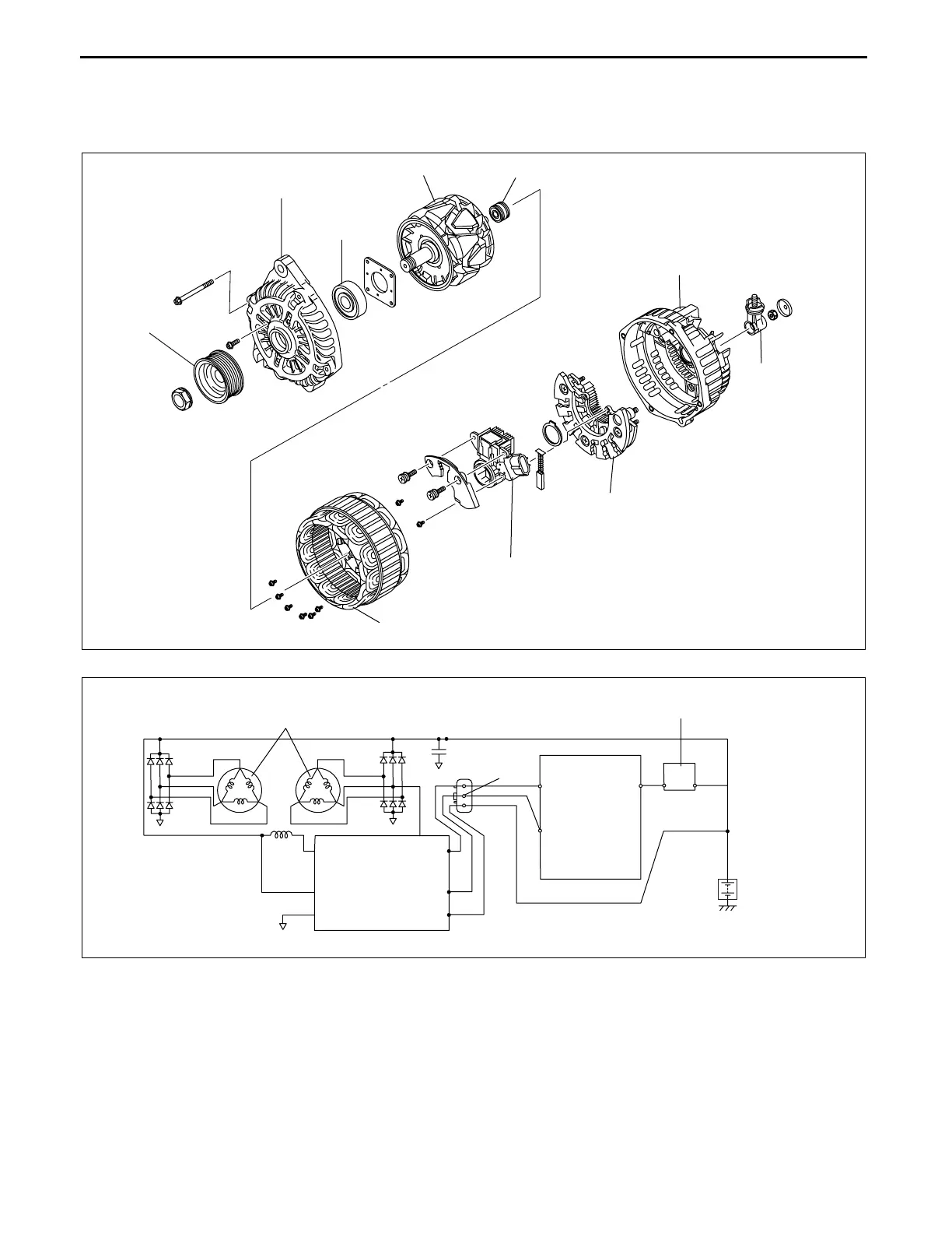
GENERATOR CONSTRUCTION [MZI-3.5]
id0117d1102300
• An IC regulator is built into the generator which determines the control voltage according to the duty signal sent
from the PCM to generator, and controls output.
• Two delta connection type stator coils have been adopted.
Terminal B circuit
• Generator output is supplied to the battery from terminal B, and to each electronic device.
Terminal RC circuit
• The terminal RC circuit is the circuit where the duty signal (Generator Regulator Control (GENRC) signal) from
the PCM is input to the IC regulator. The IC regulator control voltage is determined according to the GENRC
signal.
Terminal LI circuit
• The terminal LI circuit outputs the duty signal (Generator Load Input (GENLI) signal) of the field coil to the
PCM. The GENLI signal is used as the feedback signal which corresponds to the GENRC signal input from the
PCM. The PCM changes the duty value of the GENRC signal according to the GENLI signal. If the output is not
normal, a 0 % duty value is output to the PCM which then illuminates the generator warning light.
PULLEY
FRONT COVER
FRONT
BEARING
ROTOR
REAR BEARING
STATOR COIL
REAR COVER
TERMINAL B
COMPONENT
RECTIFIER
REGULATOR COMPONENT
(BUILT-IN POWER TRANSISTOR)
ac9uun00000486
PCM
BATTERY
IC REGULATOR
B
GENERATOR
WARNING LIGHT
STATOR COIL
LI
A
RC
ac9uun00000487
3423-1U-06H(01-17).fm 2 ページ 2006年11月22日 水曜日 午後1時47分
 Loading...