10 Interface assignment
10.1 Pinout of the terminal block on the bottom of the device
- 0V DC connection
+ Power source connection 10-30V DC
FE Functional earth
I/O
Digital Input 1 (10 - 30V DC)
1
*
Digital Output 1 (max. 0.5 A @24 V)
Digital Input 1 (10 - 30V DC)
2
*
Digital Output 1 (max. 0.5 A @24 V)
* I/O 1 and I/O 2 can be configured independently of each other
as digital input or digital output.
Image 1: Terminal strip on the bottom side
Image 2: Example: I/O 1 = input, I/O 2 = output
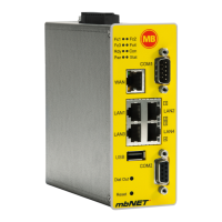
10.2 Pinout of LAN/WAN ports on the front panel of the device
Signal
1 TX+
2 TX-
3 RX+
4 Not connected
5 Not connected
6 RX-
10.3 Pinout of the USB port on the front panel of the device
Signal
1 VCC (+5V)
2 - Data
3 +Data
4 GND
Page 18 von 131 | Version: 2.2.1 - EN | Mar 28
th
, 2022 |
 Loading...