11 Getting started
The device is intended to be installed in switch cabinets and designed to be mounted on top-hat rails (ac-
cording to DIN EN 50 022).
DIN rail mounting:
Insert the device into the DIN rail. To do this, position the upper guide of
the bracket on the rail on the back of the device and then press the de-
vice downwards against the rail until fully inserted.
Depending on the device, connect an antenna, and insert a SIM card.
NOTICE
The SIM card used must be Internet- / VPN-enabled. If you have any questions, contact your cell phone
operator.
Connect the mbNET.mini to the power supply
NOTICE
Before connecting the device to a network or PC, first ensure that it is properly connected to a power supply,
otherwise it may cause damage to other equipment.
You should therefore follow the instructions given below.
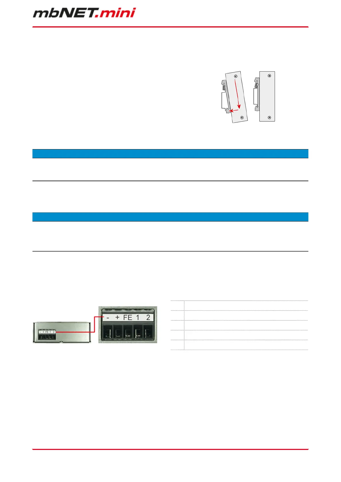
1. Connect equipotential bonding to the functional earth (FE).
2. Then connect the device to a supply voltage (10 - 30 VDC).
Make sure the polarity is correct!
- 0 V DC connection
+ Power source connection 10 - 30 V DC
FE Functional earth
1* I/O 1
2* I/O 2
* I/O 1 and I/O 2 can be configured independently of each other as digital input or digital output.
Getting started | Page 19 of 131
 Loading...