Chapter 1 M5-N Servo System Selection
5.The name and introduction of each part of the servo drive
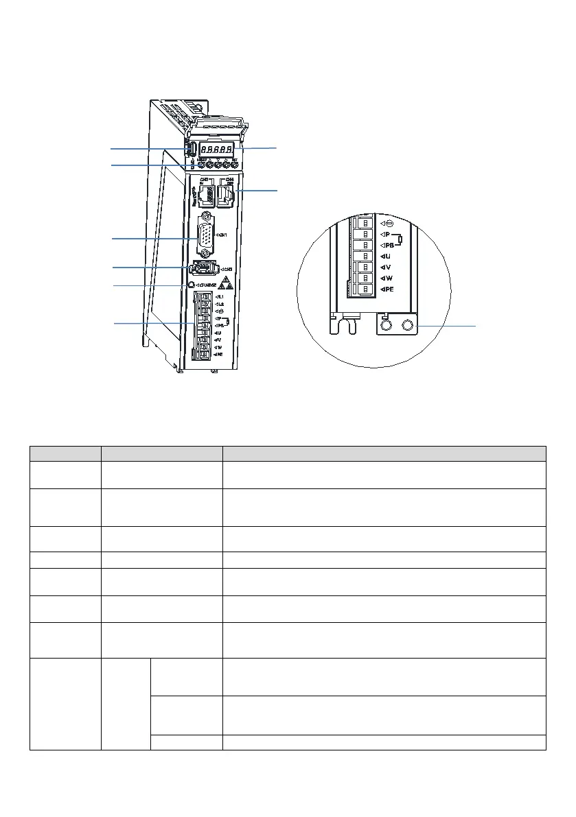
Fig.1-5 Schematic diagram of each part of M5-N servo drive (SIZEA)
Table 1-1 Description of each part of M5-N servo drive (SIZEA)
CN3, CN4
Communication interface
Two RJ45 ports for EtherCAT communication
CN5
Type-C USB
communication port
Connect the USB of the computer through this port, you can adjust the
parameters of the drive and debug the performance.
5-digit 8-segment digital tube for status monitoring, parameter display and
setting.
5 keys for parameter adjustment and display status switching, etc.
DB15 female connector, control IO interface, used to connect with external IO
and host controller.
1394 female connector for connecting motor encoder
CHARGE
Bus power indicator
It is used to indicate the state of the bus power. The indicator light indicates
that the capacitor of the bus is charged. Do not touch the power terminal even
if the main power supply is cut off to avoid electric shock.
L1, L2
Main power
supply input
Main power supply input, single-phase 220V.
DC bus terminal for common bus connection
Braking resistor wiring terminals, connect between P and PB for external
 Loading...