62Z8082A
End a
005 111
MAIN:
Curr. IP,max,a p.u.
[ 005 111 ]
MAIN:
IP,max p.u.,delay a
[ 005 163 ]
MAIN:
Curr. IP,max,a p.u.
[ 005 111 ]
MAIN:
IP,max p.u.,stored a
[ 005 160 ]
MAIN:
Curr. IP,max,a p.u.
[ 005 111 ]
MAIN:
IP,max p.u.,stored a
[ 005 160 ]
MAIN:
Settl. t. IP,max,del
[ 010 113 ]
MAIN:
Settl. t. IP,max,del
[ 010 113 ]
MAIN:
Settl. t. IP,max,del
[ 010 113 ]
MAIN:
Settl. t. IP,max,del
[ 010 113 ]
MAIN:
Settl. t. IP,max,del
[ 010 113 ]
MAIN:
Settl. t. IP,max,del
[ 010 113 ]
MAIN:
Reset IP,max,st.USER
[ 003 033 ]
MAIN:
Curr. IP,max,a p.u.
005 160
MAIN:
IP,max p.u.,stored a
005 163
MAIN:
IP,max p.u.,delay a
End b
005 112
MAIN:
Curr. IP,max,b p.u.
006 160
MAIN:
IP,max p.u.,stored b
006 163
MAIN:
IP,max p.u.,delay b
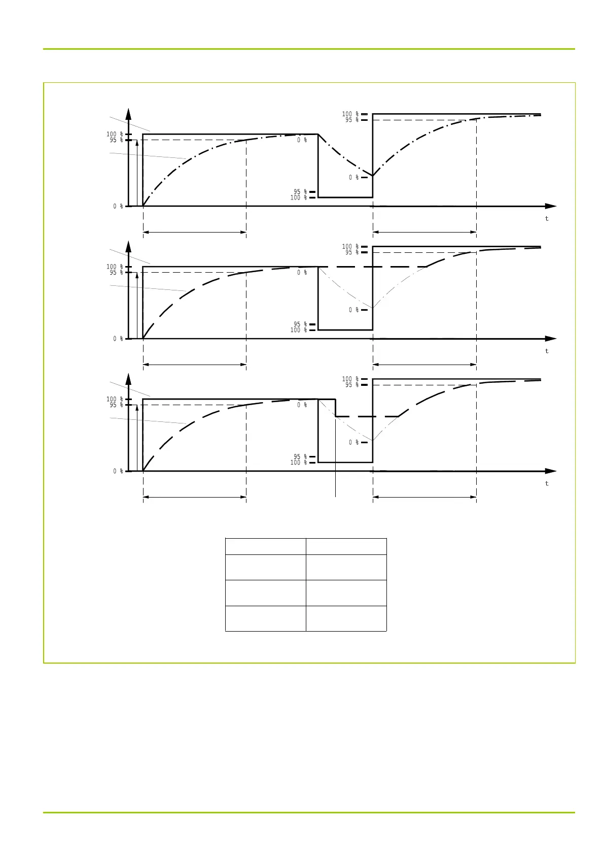
Fig. 3-43: Operation of delayed and stored maximum phase current display, shown here for end a
3.12.3.2.1 Measured Operating Data for the Phase Currents
The following diagram shows the measured operating data for the phase
currents, using the transformer end a as an example.
The parameters given apply to transformer end a. The corresponding parameters
of the other transformer ends are given in Chapter 7, (p. 7-1) and Chapter 8,
(p. 8-1).
3 Operation
P631
P631/EN M/R-11-C // P631-310-650 3-69