64Z8046A
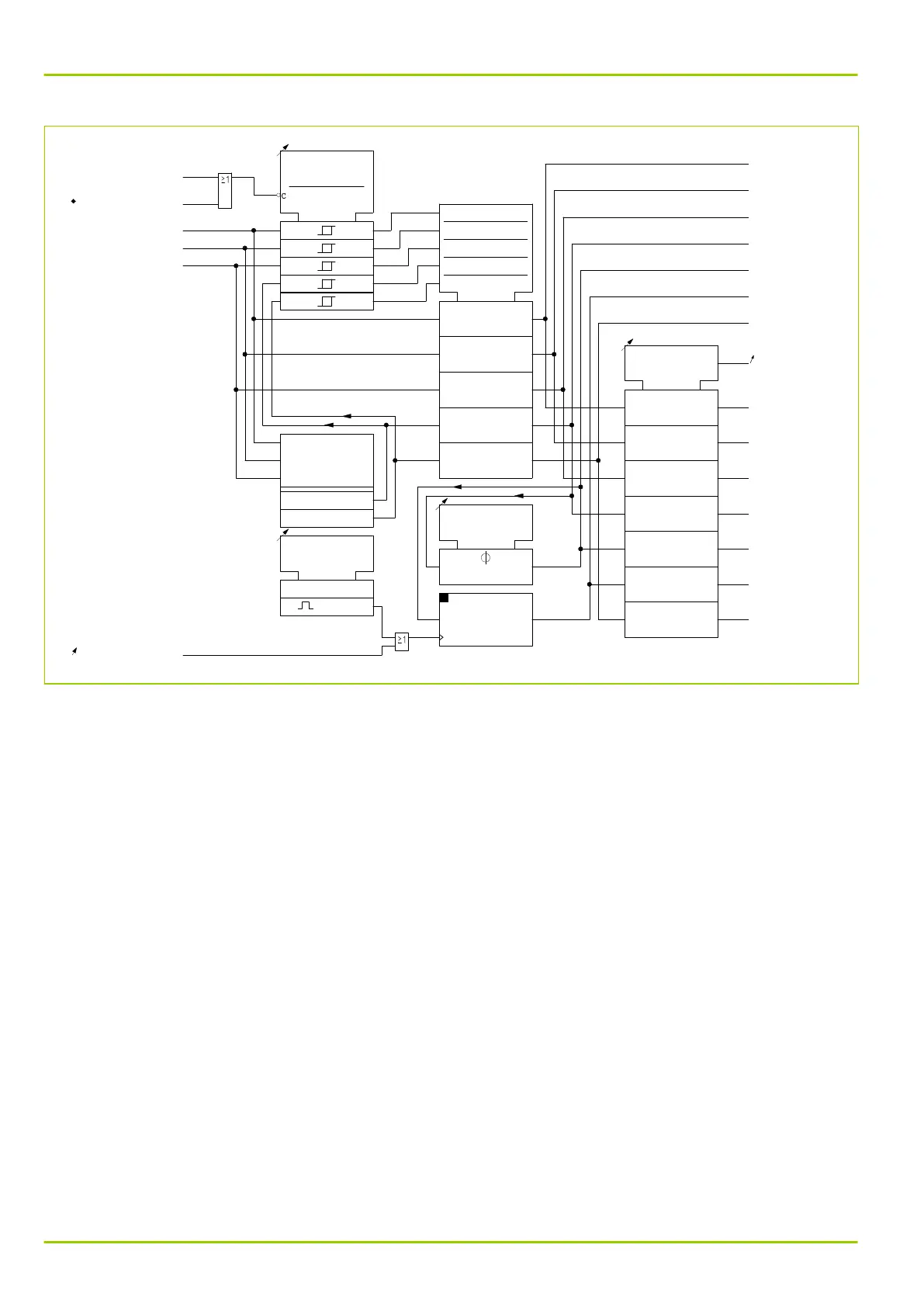
MAIN:
General starting
[ 036 000 ]
MAIN:
Current IA,a p.u.
MAIN:
Current IB,a p.u.
MAIN:
Current IC,a p.u.
MAIN:
Curr. IP,max,a p.u.
MAIN:
IP,max p.u.,stored a
MAIN:
IP,max p.u.,delay a
MAIN:
Curr. IP,min,a p.u.
MAIN:
Inom C.T.prim.,end a
MAIN:
Inom C.T.prim.,end a
MAIN:
Current IA,a prim.
MAIN:
Current IB,a prim.
MAIN:
Current IC,a prim.
MAIN:
Curr. IP,max,a prim.
MAIN:
IP,max prim.,delay a
MAIN:
IP,max prim.stored a
MAIN:
Curr. IP,min,a prim.
MAIN:
Meas. value rel. IP
[ 011 030 ]
MAIN:
Settl. t. IP,max,del
[ 010 113 ]
MAIN:
Reset IP,max,st.USER
[ 003 033 ]
0
1
0: don't execute
1: execute
MAIN:
General reset USER
[ 003 002 ]
1: execute
MAIN:
Hardware fault
306 018
IA,z
IB,z
IC,z
Imax,z
Imin,z
COMP
c1
c2
c3
c4
c5
1
2
3
4
5
R
Fig. 3-44: Measured operating data for the phase currents, shown here for end a
3.12.3.2.2 Measured Operating Data for the Residual Currents
The following diagram shows the measured operating data for the residual
currents.
The parameters given apply to transformer end a. The corresponding parameters
of transformer end b are given in Chapter 7, (p. 7-1) and Chapter 8, (p. 8-
1).
P631
3 Operation
3-70 P631/EN M/R-11-C // P631-310-650