Parameter Address
Default Min Max Unit Logic Diagram
Binary input
INP: State U 701
152 108
0: "Low"
[spacer]
INP: State U 702
152 111
0: "Low"
[spacer]
INP: State U 703
152 114
0: "Low"
[spacer]
INP: State U 704
152 117
0: "Low"
[spacer]
INP: State U 705
152 120
0: "Low"
[spacer]
INP: State U 706
152 123
0: "Low"
[spacer]
INP: State U 901
152 144
0: "Low"
[spacer]
INP: State U 902
152 147
0: "Low"
[spacer]
INP: State U 903
152 150
0: "Low"
[spacer]
INP: State U 904
152 153
0: "Low"
[spacer]
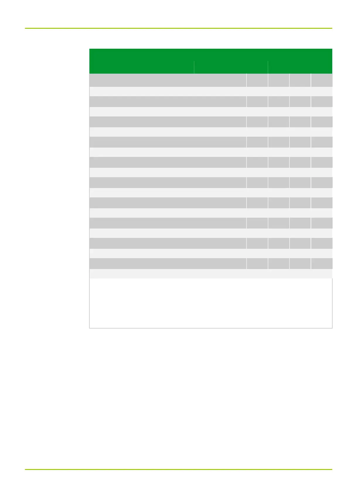
The state of the binary signal inputs is displayed as follows:
●
Without function: No functions are assigned to the binary signal input.
●
"Low": Not energized.
●
"High": Energized.
This display appears regardless of the setting for the binary signal input mode.
8 Information and Control Functions
P631
P631/EN M/R-11-C // P631-310-650 8-21