Parameter Address
Default Min Max Unit Logic Diagram
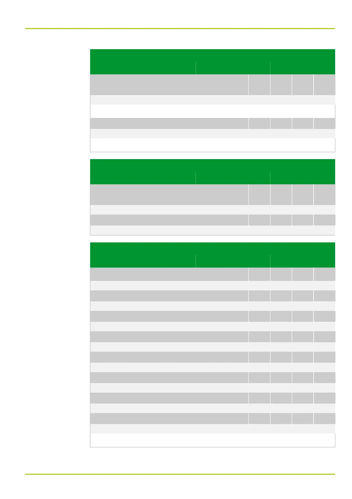
Circuit breaker
failure protection
CBF_1: Enable USER
003 016
0: don't execute Fig. 3-126, (p. 3-159)
[spacer]
Circuit breaker failure protection is enabled from the local control panel.
[spacer]
CBF_1: Disable USER
003 015
0: don't execute Fig. 3-126, (p. 3-159)
[spacer]
Circuit breaker failure protection is disabled from the local control panel.
Parameter Address
Default Min Max Unit Logic Diagram
Circuit breaker
failure protection
CBF_2: Enable USER
003 124
0: don't execute
[spacer]
CBF_2: Disable USER
003 123
0: don't execute
Parameter Address
Default Min Max Unit Logic Diagram
Programmable Logic
LOGIC: Trigger 1
034 038
0: don't execute Fig. 3-141, (p. 3-174)
[spacer]
LOGIC: Trigger 2
034 039
0: don't execute
[spacer]
LOGIC: Trigger 3
034 040
0: don't execute
[spacer]
LOGIC: Trigger 4
034 041
0: don't execute
[spacer]
LOGIC: Trigger 5
034 042
0: don't execute
[spacer]
LOGIC: Trigger 6
034 043
0: don't execute
[spacer]
LOGIC: Trigger 7
034 044
0: don't execute
[spacer]
LOGIC: Trigger 8
034 045
0: don't execute Fig. 3-141, (p. 3-174)
[spacer]
Intervention in the logic at the appropriate point by a 100 ms pulse.
8 Information and Control Functions
P631
P631/EN M/R-11-C // P631-310-650 8-91