Page 26
Installation
optoNCDT 1420
5.1.3 Optimizing the Measuring Accuracy
Color strips Direction of movement
Grinding or rolling marks
llaasseerr ooffff
iinn rraannggee
mmiiddrraannggee
eerrrroorr
ssttaattee
oouuttppuutt
sseelleecctt
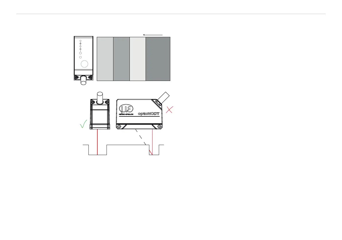
In case of rolled or polished metals that are moved
past the sensor the sensor plane must be arranged
in the direction of the rolling or grinding marks. The
same arrangement must be used for color strips.
Fig. 10 Sensor arrangement in case of ground or
striped surfaces
correct
incorrect
(shadow)
In case of bore holes, blind holes and edges in
the surface of moving targets the sensor must
be arranged in such a way that the edges do not
obscure the laser spot.
Fig. 11 Sensor arrangement for holes and ridges
 Loading...