Page 91
Appendix| Factory Setting
optoNCDT 1420
A 2 Factory Setting
Password „000“ Measurement averaging Median 9
Measuring rate 2 kHz Output Analog current
Measuring range
100 % FSO: I = 20 mA , digital 64877 RS422 921.6 kBaud
0 % FSO: I = 4 mA, digital 643 Trigger mode No trigger
Peak selection Highest peak Language German
Error handling Error output, no measurement
LED State normal operation
Key Select
Supply
voltage
red
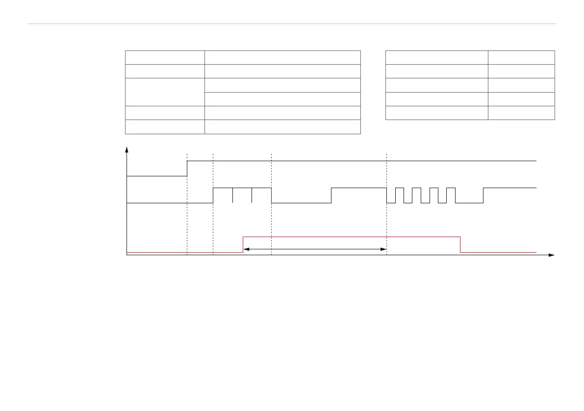
flashes yellow approx. 8 Hzflashes yellow approx. 1 Hz
yellow green
t
0
10 ... <15 st
1
t
3
t
2
10 s
t
4
Fig. 50 Flow chart to start a sensor with factory setting
t
0
: power supply is on
t
1
... t
3
: both LEDs signalize the start sequence (red-yellow-green for 1 sec. each)
t
2
: key is pressed during start sequence (t
1
... t
3
)
t
4
: key is released while the LED State is flashing yellow
Dt = t
4
- t
2
; Dt (key press period) must be at least 10 sec., max. 15 sec.
 Loading...