Page 37
Installation
optoNCDT 1420
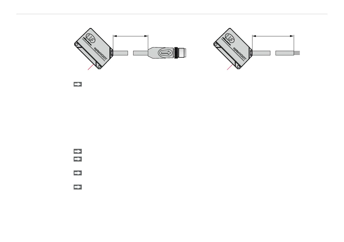
5.4.9 Connector and Sensor Cable
0.3 m
3 m
ILD 1420 with pigtail ILD 1420 with open ends
Never fall below the bending radius for the sensor cable of 30 mm (fixed) resp. 60 mm (dynamic).
i
The fixed connected sensor cables are not cable carriers suitable.
i
Unused open cable ends must be insulated to protect against short circuits or malfunction of the sen-
sor.
MICRO-EPSILON recommends to use the cable carriers suitable standard connection cable of the optional
accessories, see Chap. A 1.
Mount the 12-pin M12 cable connector if you use a cable carriers suitable sensor cable PCF1420.
Avoid excessive pulling to the cables. Provide strain relieves near the connectors when cables > 5 m are
vertically free hanging.
Connect the cable shield to the potential equalization (PE, protective earth conductor) on the evaluator
(control cabinet, PC housing) and avoid ground loops.
Never lay signal leads next to or together with power cables or pulse-loaded cables (e.g. for drive units
and solenoid valves) in a bundle or in cable ducts. Always use separate ducts.
Recommendedstrandcross-sectionforself-madeconnectioncables:≥0.14mm²(AWG25).
 Loading...