Page 62
Set Sensor Parameter
optoNCDT 1420
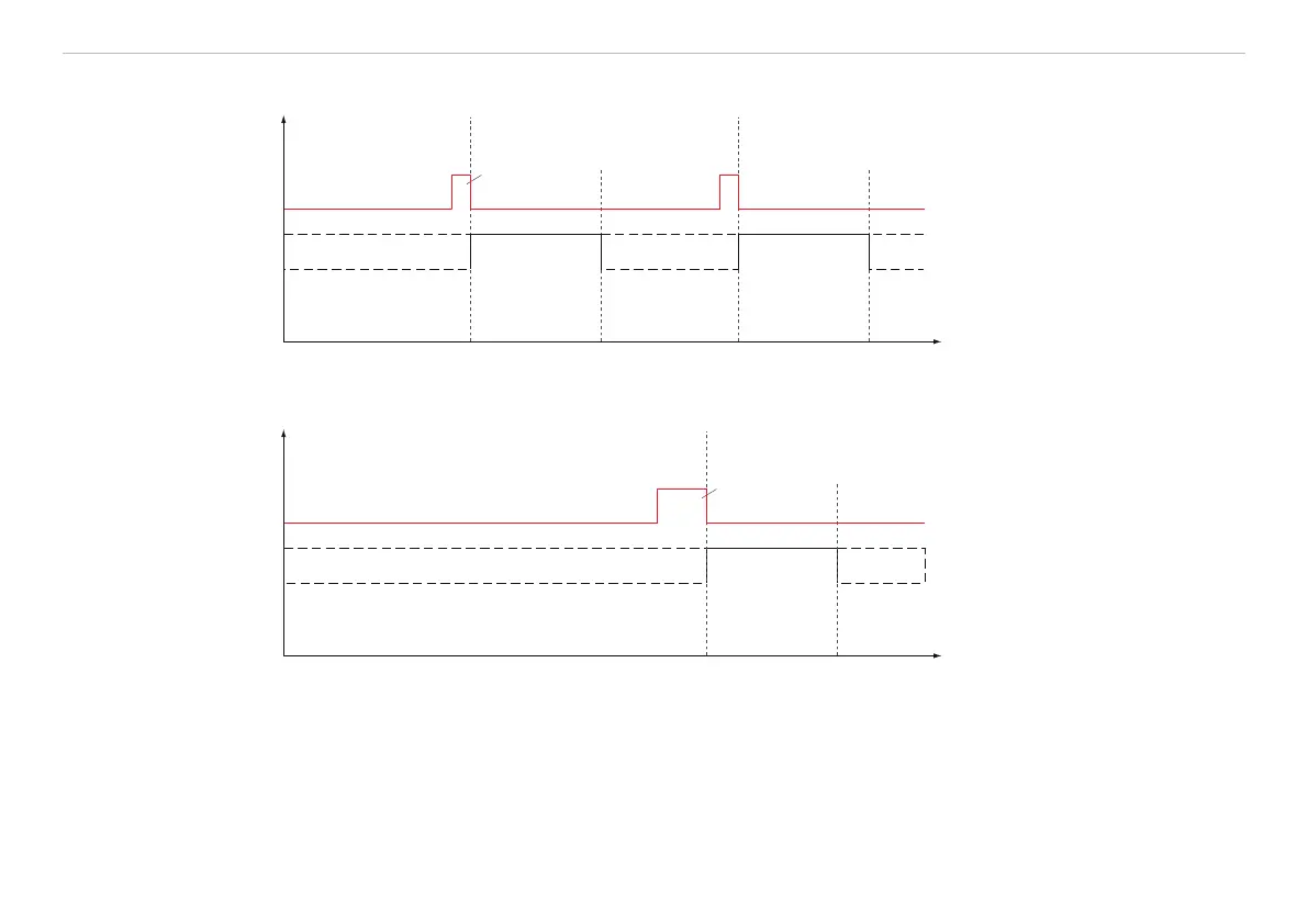
7.4.9.2 Zeroing, Mastering with Hardware Input
LED state
Measuring
Green, red
1
, yellow,
depends on
measuring position.
yellow yellow
Pin 9
(violet)
Pin 9
(violet)
t
0
2 s t
1
t
2
2 s t
3
30 ms ... <3 s
i
A pulse on the function-
al input can be made
via pin 9 pigtail resp.
via the violet wire on
the sensor cable resp.
via the PCF1420-x.
Details of the hardware
input can be found in
the electrical connec-
tions, see Chap. 5.4.6.
Fig. 35 Flow chart for zeroing, mastering (hardware input)
LED state
Measuring
Green, red, yellow,
depends on
measuring position
yellow
Pin 9
(violet)
t
0
2 s t
1
5 s ... <10 s
Fig. 36 Flow chart for the return of zero setting and mastering
The function zeroing/mastering can be applied successive in several times. Between repeating the zeroing/
mastering function a pause of 1 s is required. The zeroing/mastering function can also be combined with the
select key.
1) With red State LED, the master value is not accepted, flashes with 8 Hz for 2 s.
 Loading...