Page 34
Installation
optoNCDT 1420
5.4.5 Analog Output
The sensor provides a current output 4 ... 20 mA.
i
The output may not be continuously operated in short circuit operation without load resistor. The short
circuit operation leads to durable thermal overload and thus for automatic overload shutdown of the
output.
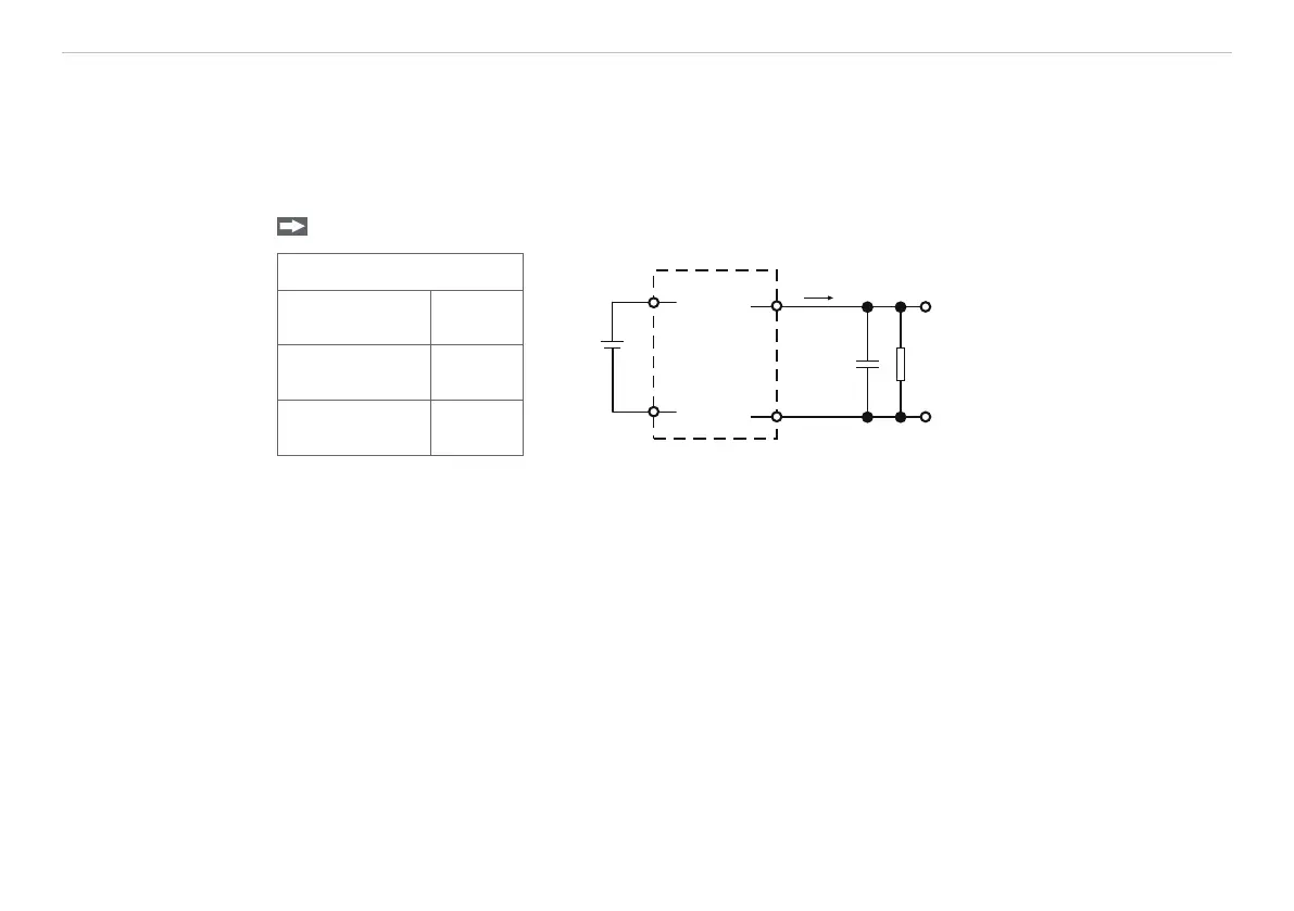
Connect the output 11 (white) and 12 (blue) on the sensor to a measuring device.
Sensor
11
U
out
R
1
C
1
100 nF
12
ILD1420
I
out
7
12
11...
30 VDC
When using a PCF1420-x/U
you will get an analog voltage
at the output in the range of
1 ... 5 V.
R = 250 Ohm:
U
OUT
1 ... 5 V at U
B
> 11 V
R = 500 Ohm:
U
OUT
2 ... 10 V at U
B
> 17 V
12-pin M12
cable connector
Sensor
cable
I
OUT
(Pin 11)
white
GND (Pin 12) blue
Fig. 19 Wiring for voltage output
1) The components are already included in PCF 1420-x/U.
 Loading...