Page 36
Installation
optoNCDT 1420
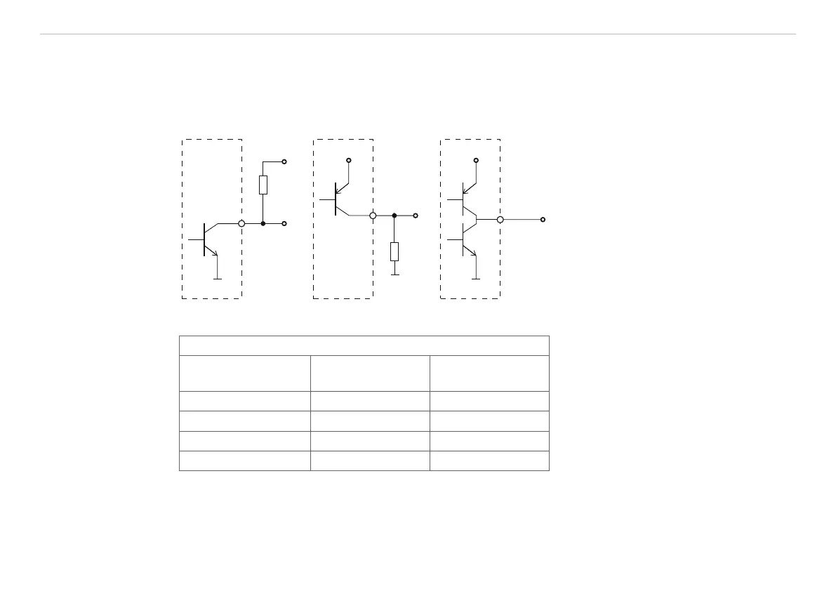
5.4.8 Digital Output
The switching characteristic (NPN, PNP, Push-Pull, Push-Pull negated) of the digital output (Error) depends
on the programing.
The NPN output is e.g. suitable for adjustment to TTL logics with an auxiliary voltage U
H
= +5 V. The digital
output is protected against reverse polarity, overloading (< 100 mA) and over temperature.
NPN
+U
R
L
H
10
brown
PNP
10
brown
+U
B
Push-Pull
+U
B
10
brown
R
L
Output is not galvanically isolated.
24V logics (HTL),
I
max
= 100 mA,
U
Hmax
= 30 V saturation voltage at I
max
=
100 mA:
Low < 2.5 V (output - GND),
High < 2.5 V (output - +U
B
)
Fig. 22 Electrical wiring digital output
Switching characteristic
Description Output active
(error)
Output passive
(no error)
NPN (Low side) GND appr. +U
H
PNP (High side) + U
B
appr. GND
Push-Pull + U
B
GND
Push-Pull, negated GND + U
B
Fig. 23 Switching characteristic digital output
Digital output is activated when measuring object is missing, measuring object too close/too far or when no
valid measurement value can be determined.
 Loading...