Page 71
Set Sensor Parameter
optoNCDT 1420
7.5.3.3 Output Scaling via Hardware Input
Scaling of the analog output can be made via an impulse at the functional input, pin 9 pigtail resp. via the
violet wire on the sensor cable resp. PCF1420-x.
Pin 9 (violet)
LED state
Error
Measuring
Green, red, yellow,
depends on
measuring position
Color according
to measuring
position
flashes red
approx. 1 Hz
flashes green
approx. 1 Hz
Start
teaching
Position the
measuring object
to 4 mA
Positon the
measuring
object to 20 mA
Teach-in 1 Teach-in 2 Measuring
red
t
0
5 min 2 s 2 s 2 s30 s 30 st
1
t
3
t
2
t
4
t
5
t
7
t
8
t
9
t
6
yellow yellow
min.
30 ms
min.
30 ms
min.
1 ms
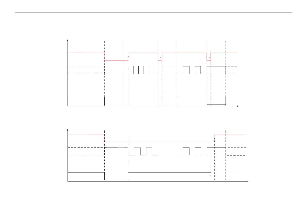
Fig. 42 Flow chart for output scaling
LED state
Measuring
Green, red, yellow,
depends on
measuring position
Color according
to measuring
position
Flashes red approx. 1 Hz
Measuring
red
t
0
5 min 2 s
200 ms t
5
- t
3
= 2 s
5 ... <10 st
1
t
2
t
3
t
4
t
5
yellow
Error
Pin 9 (violet)
Fig. 43 Flow chart for the return of output scaling
 Loading...