No. Name Function and Connection
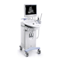
1 Monitor Displays images and parameters, etc.
2 Hook for transducer cable Used for hanging the transducer cable.
3
Transducer and gel bottle
holder
Used for holding the transducer or gel bottle
provisionally.
4 Printer area Used for mounting a printer.
5 Video output Connects to the video input port of the video printer.
6 AC out Connects to the power cord of the video printer.
7 Remote Connects to the remote control port of the video printer.
8 Transducer socket Used for connecting a transducer.
9 Footswitch port Connects a footswitch.
10 Casters Used for locking or moving the system.
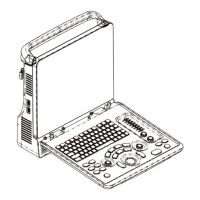
11 Control panel Refer to “1.4.3 Control Panel” for details.
12 Handle Used for moving the system.
13 USB port
Used for connecting a USB device.
For systems with optical disc drive, the USB ports locate
under the power switch, of which the lower one is
reserved.
For systems without optical disc drive, the USB ports
locate to the left of the power switch.
14 Power switch Power on / off
15 Optical disc drive (optional) Backs up/restores data
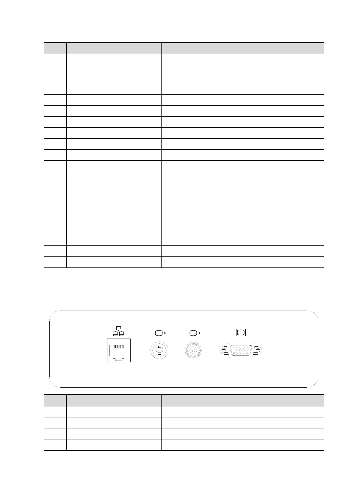
1.4.2 I/O Panel
The I/O panel locates at the back of the system.
1
2 3 4
No. Name Function
1 Network port Accepts the network cable.
2 Video out (S-video) Connects to the video input port of the video printer.
3 Video out (coaxial connector) Connects to the video input port of the video printer.
4 VGA out Connects an external monitor.
Overview 1-5