412
12 DATA USED FOR POSITIONING CONTROL
12.3 Basic Setting
[Pr.150] Input terminal logic selection
Set the external input signal logic (upper/lower limit signal, stop signal, near-point dog signal, and external command/
switching signal) from the external device of the Simple Motion module.
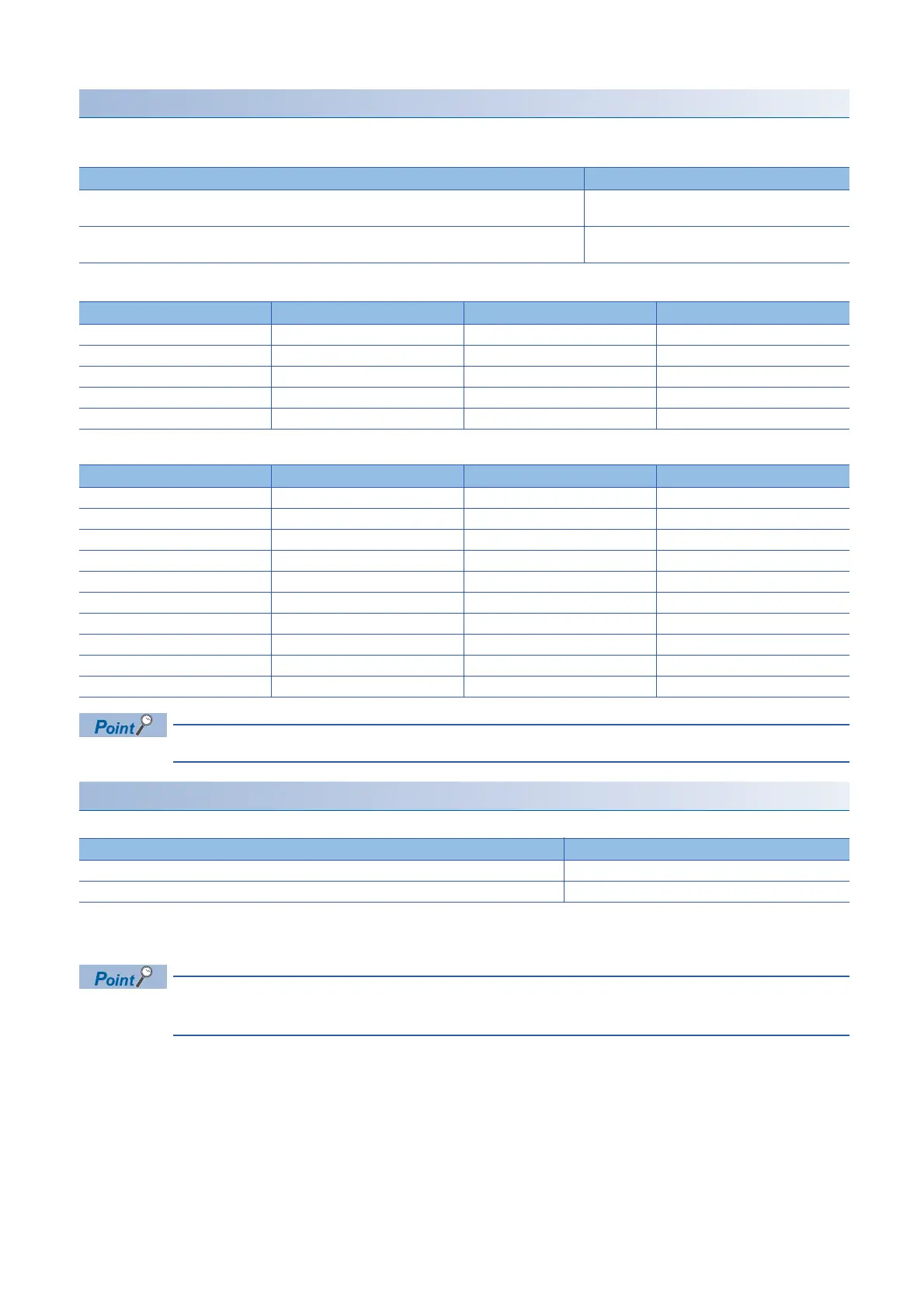
■RD77MS2
■RD77MS4/8/16
A mismatch in the setting may disable normal operation. Be careful when changing the default value.
[Pr.151] Manual pulse generator/INC synchronous encoder input logic selection
Set the input signal logic from the manual pulse generator/incremental synchronous encoder.
Refer to the following for the negative logic/positive logic.
Page 409 [Pr.24] Manual pulse generator/Incremental synchronous encoder input selection
A mismatch in the signal logic will disable normal operation. Be careful of this when you change from the
default value.
Input terminal logic selection Setting value
ON at leading edge (When the current is flowed through the input signal terminal: ON, When the current
is not flowed through the input signal terminal: OFF)
0
ON at trailing edge (When the current is flowed through the input signal terminal: OFF, When the
current is not flowed through the input signal terminal: ON)
1
Bit Input terminal Bit Input terminal
b0 SIN1 b5 SIN6
b1 SIN2 b6 SIN7
b2 SIN3 b7 SIN8
b3 SIN4 b8 SIN9
b4 SIN5 b9 SIN10
Bit Input terminal Bit Input terminal
b0 SIN1 b10 SIN11
b1 SIN2 b11 SIN12
b2 SIN3 b12 SIN13
b3 SIN4 b13 SIN14
b4 SIN5 b14 SIN15
b5 SIN6 b15 SIN16
b6 SIN7 b16 SIN17
b7 SIN8 b17 SIN18
b8 SIN9 b18 SIN19
b9 SIN10 b19 SIN20
Manual pulse generator/Incremental synchronous encoder input logic selection Setting value
Negative logic 0
Positive logic 1

 Loading...