FX Series Positioning Controllers Introduction 1
1-22
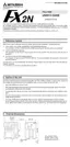
Cable to connect general-purpose drive unit E-GM-200CAB
I/O cables FX-16E-150CAB, FX-16E-300CAB, FX-16E-500CAB, FX-16E-150CAB-R,
FX-16E-300CAB-R, FX-16E-500CAB-R
• The figures above indicate the pin assignment when the connector is seen from the side on
which the positioning unit/extension block/terminal block is connected (engaged).
ST2/ST4
SVRDY
COM2/COM6
COM2/COM6
SVEND
COM4/COM8
PG0
FP
COM5/COM9
RP
CLR
COM3/COM7
ST1/ST3
COM5/COM9
1
6
4
1
2
12
11
14
6
19
16
10
13
9
3
2
11
14
13
19
16
10
20 20
4
Connected to drive
unit of general-purpose
servo motor or stepping
motor via FX-16E-TB
11
1
20
10
Green (0.5 mm )
VIN
VIN
77
17 17
VIN
VIN
88
18 18
55
15 15
12
9
3
Shielded cable
Class 3 grounding
2
Never use them.
Connected to CON2
in FX2N-10GM or
CON3/CON4 in
FX
2N-20GM
Pin assignment
1
2
3
4
5
6
7
8
9
10
11
12
13
14
15
16
17
18
19
20
1
2
3
4
5
6
7
8
9
10
11
12
13
14
15
16
17
18
19
20
Connector on
positioning
unit/extension
block side
1
2
3
4
5
6
7
8
9
10
11
12
13
14
15
16
17
18
19
20
Protrusion
Connector on
terminal block
side
1
2
3
4
5
6
7
8
9
10
11
12
13
14
15
16
17
18
19
20
Protrusion

 Loading...